Bently Nevada 330905-00-11-10-02-CN Retrofit-Ready Proximity Probe for 3300 NSv Control Systems
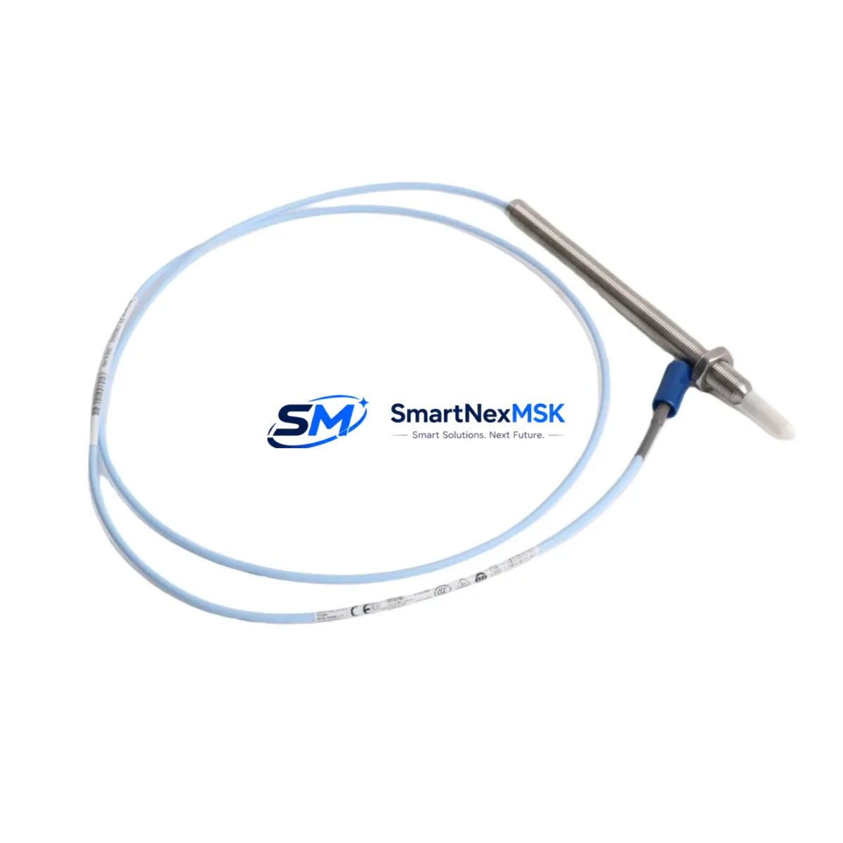
The Bently Nevada 330905-00-11-10-02-CN is an 8mm eddy-current proximity probe engineered for continuous shaft vibration and position monitoring within the Bently Nevada 3300 NSv series platform. As legacy 3300 XL and earlier 3300 NSv installations approach end-of-service milestones, this probe serves as the primary retrofit-ready replacement, offering full electrical and mechanical compatibility with existing field wiring, connector pinouts, and monitor channel configurations. Whether you are executing a planned control-system modernization or responding to an unplanned probe failure on a critical rotating machine, the 330905-00-11-10-02-CN is stocked and ready for immediate dispatch with a 12-month warranty covering manufacturing defects and calibration integrity.
Upgrade Compatibility Table
| Parameter | Details |
|---|---|
| Replacement For | Bently Nevada 330905-00-11-10-02-CN (same SKU, current production revision) |
| Compatible Monitor | Bently Nevada 3300 NSv Proximitor / Seismic Monitor |
| Probe Diameter | 8 mm eddy-current tip |
| Cable Length | 1.0 m integral cable (extension cable 330130-080-00-00 required for longer runs) |
| Connector Interface | Standard 3300 NSv coaxial connector — no adapter required |
| Installation Requirement | M10 × 1.0 threaded boss; gap voltage –10.0 VDC at 1.0 mm nominal |
| Communication Compatibility | Analog 4–20 mA / voltage output to System 1 Evolution or 3500 rack via existing field wiring |
| Retrofit Recommendation | Direct drop-in; re-verify gap voltage and sensitivity after installation |
| Commissioning Focus | Gap voltage check, OK relay verification, channel bypass during hot-swap |
| Warranty | 12 months from shipment date — covers manufacturing defects and calibration |
Retrofit Planning for Existing Automation Systems
Successful integration of the 330905-00-11-10-02-CN into an aging control architecture requires a structured pre-installation audit. Begin by confirming that the host monitor — typically a Bently Nevada 3300 NSv Proximitor / Seismic Monitor installed in a 3300 NSv rack — is operating within its rated input impedance range. If the existing rack is a mixed-slot configuration housing both vibration and temperature channels, verify that adjacent I/O modules have not drifted in their baseline calibration, as cross-channel interference can mask a genuine probe fault.
Field wiring from the probe tip to the Proximitor input should be inspected for insulation breakdown, particularly in high-temperature or chemically aggressive environments. The integral 1.0 m cable on the 330905-00-11-10-02-CN mates directly with the Bently Nevada 330130-080-00-00 extension cable, preserving the coaxial shielding continuity that is critical for low-noise gap voltage readings. Where cable runs exceed the standard extension length, a second extension segment may be added, but total cable capacitance must remain within the Proximitor’s specified range.
For sites migrating from an older 3300 XL platform to the 3300 NSv architecture, the power supply module within the rack — often a dedicated 24 VDC or 28 VDC Proximitor power conditioner — must be confirmed capable of sourcing the additional quiescent current drawn by the new probe. In parallel, the 3500/22M Transient Data Interface or equivalent data-acquisition card should be checked for firmware compatibility with the updated probe sensitivity constant (–7.87 V/mm nominal for 8 mm probes).
HMI screens built on System 1 Evolution or legacy System 1 v6.x should be reviewed to confirm that the probe tag, engineering-unit scaling, and alarm setpoints reference the correct sensitivity value. A mismatch between the programmed sensitivity and the physical probe constant will produce offset readings that may suppress genuine vibration alarms or generate nuisance trips. Where the control narrative was originally written for a 5 mm probe, the entire alarm philosophy — including danger, alert, and OK relay thresholds — must be recalculated before the 8 mm 330905-00-11-10-02-CN is placed in service.
Communication links between the 3300 NSv rack and the plant DCS — whether via Modbus RTU over RS-485, Modbus TCP/IP, or a 4–20 mA hardwired loop — should be tested under simulated vibration conditions before the machine is returned to service. If the site uses a Bently Nevada 3500/92 Communication Gateway, confirm that the gateway firmware supports the channel-count and data-rate requirements of the upgraded rack configuration. For plants integrating into a broader ABB, Emerson DeltaV, or Honeywell Experion PKS environment, the OPC DA or OPC UA server mapping for the new probe channel must be validated against the existing process historian tags.
Spare-parts planning should account for the full probe assembly: the 330905-00-11-10-02-CN probe body, the 330130-080-00-00 extension cable, and the matching Proximitor sensor (typically 330180-X1-05 or 330180-X1-CN for the NSv platform). Stocking a complete probe-cable-Proximitor set minimises mean time to repair during unplanned outages on critical compressors, turbines, or pump trains.
Downtime Control During System Migration
Minimising production interruption during a proximity probe replacement begins with pre-staging all components — probe, extension cable, calibration tool, and gap-setting gauge — at the machine before the maintenance window opens. Where the 3300 NSv monitor supports channel bypass or inhibit mode, activate the bypass on the target channel before breaking the coaxial connection. This prevents the monitor from issuing a spurious danger trip to the turbine control system or DCS interlock logic while the probe is disconnected.
With the channel inhibited, remove the legacy probe, clean the threaded boss, and install the 330905-00-11-10-02-CN to the manufacturer’s torque specification. Reconnect the extension cable and verify gap voltage at the Proximitor front-panel test point — target –10.0 VDC ± 0.5 V at 1.0 mm air gap. Once gap voltage is confirmed, release the channel inhibit and observe the OK relay status. A steady OK indication confirms that the probe, cable, and Proximitor are operating as an integrated measurement chain.
Original PLC ladder logic or function-block programs that reference the vibration channel — whether in a Rockwell Automation ControlLogix, Siemens S7-300, or GE Fanuc Series 90 controller — do not require modification, provided the analog input scaling in the controller matches the probe sensitivity constant. Confirm the 4–20 mA span corresponds to the correct engineering-unit range (e.g., 0–500 µm pk-pk) before releasing the machine to operations. Document the as-found and as-left gap voltage readings in the maintenance management system to establish a baseline for future condition monitoring.
Retrofit Support FAQ
Q1: Is the 330905-00-11-10-02-CN a direct replacement for earlier 3300 NSv probe revisions?
Yes. The 330905-00-11-10-02-CN is the current production revision and is electrically and mechanically interchangeable with all prior –CN suffix variants used in 3300 NSv installations. No wiring changes or adapter hardware are required. Re-verify gap voltage after installation to confirm the measurement chain is within specification.
Q2: What commissioning steps are mandatory before returning the machine to service?
At minimum: (1) confirm gap voltage at the Proximitor test point (–10.0 VDC ± 0.5 V at 1.0 mm), (2) verify OK relay status is healthy, (3) confirm channel alarm setpoints in the monitor and DCS match the probe sensitivity constant, and (4) perform a slow-roll vibration check to validate signal quality before full-speed operation.
Q3: Can this probe be used with a Bently Nevada 3500 rack instead of the 3300 NSv?
The 330905-00-11-10-02-CN is optimised for the 3300 NSv Proximitor. While the 3500 series uses compatible 8 mm probe geometry, the 3500 rack requires probes qualified to the 3500/42M or 3500/40M channel specifications. Consult the 3500 rack channel datasheet before substituting this probe in a 3500 installation.
Q4: What does the 12-month warranty cover, and how is a claim initiated?
The 12-month warranty covers manufacturing defects, calibration drift beyond published tolerances, and connector integrity failures under normal operating conditions. To initiate a claim, contact sales@smartnexmsk.com with the order number, installation date, and a description of the observed fault. Replacement units are dispatched after fault verification, with pre-shipment functional testing documented and included with each unit.
© 2026 SMARTNEXMSK. All rights reserved.
Original Source: https://smartnexmsk.com
Contact: sales@smartnexmsk.com | +86 18259474341


