Bently Nevada 330905-00-16-05-02-05 Spare 3300 XL NSv: Precision Spare for Vibration Monitoring Downtime Recovery
The Bently Nevada 330905-00-16-05-02-05 is an original eddy current proximity transducer engineered for the 3300 XL NSv (Non-contacting Vibration) monitoring system. In rotating machinery protection environments — turbines, compressors, pumps, and gearboxes — this transducer is a critical front-line sensor. When it fails or degrades, the entire vibration channel goes offline, triggering protective shutdowns or, worse, blind operation. Stocking a verified replacement is not optional; it is a core element of any serious predictive maintenance program.
At SMARTNEXMSK, every 330905-00-16-05-02-05 unit is sourced from authorized supply chains, inspected against OEM electrical specifications, and shipped with a 12-month warranty. We support maintenance engineers and procurement teams who need fast, reliable spare parts with full traceability — no substitutes, no grey-market risk.
Spare Maintenance Table
| Parameter | Specification |
|---|---|
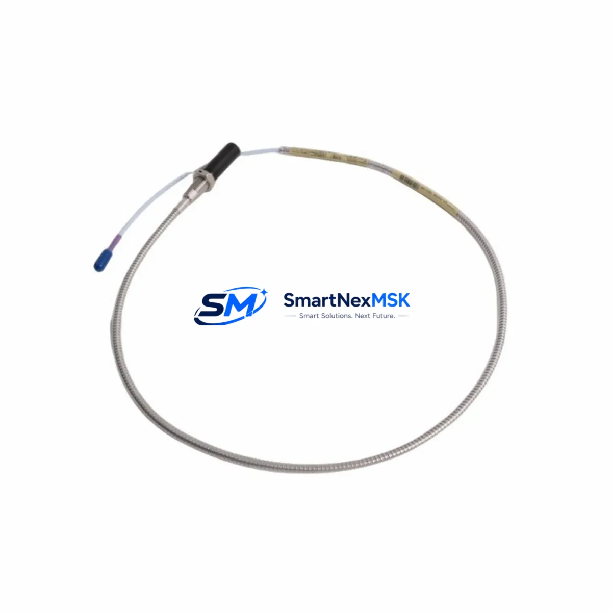
| Part Number | 330905-00-16-05-02-05 |
| Brand | Bently Nevada |
| Series | 3300 XL NSv (Non-contacting Vibration) |
| Type | Eddy Current Proximity Transducer |
| Probe Cable Length | 16 in (406 mm) — encoded in SKU segment “-16-“ |
| Extension Cable Length | 5 m — encoded in SKU segment “-05-“ |
| Connector Type | 02 (standard industrial connector) |
| Sensitivity | 200 mV/mil (7.87 V/mm) nominal |
| Operating Gap Range | 10–90 mil (0.25–2.29 mm) typical |
| Supply Voltage | −24 VDC (via 3300 XL driver/proximitor) |
| Operating Temperature | −35°C to +121°C (probe tip) |
| Target Material Compatibility | Steel, stainless steel, iron-based alloys |
| Installation | Threaded probe mount; compatible with 3300 XL proximitor housings |
| Application Environment | Turbines, compressors, pumps, gearboxes, motor shafts |
| Compliance | API 670 compatible monitoring system |
| Origin | USA |
| Warranty | 12 Months — tested before shipment |
Maintenance Planning for Continuous Operation
When a 330905-00-16-05-02-05 proximity transducer is flagged for replacement during a planned outage or emergency shutdown, experienced maintenance engineers know that the transducer itself is rarely the only component that needs attention. A complete channel inspection should cover the full signal path and associated infrastructure.
Start with the 3300 XL Proximitor/Seismic Monitor (e.g., 3300/16 or 3300/20 series modules) — the proximitor converts the transducer’s raw oscillator signal into a DC voltage proportional to gap distance. If the transducer has been running in a high-temperature or high-vibration zone, the proximitor module should be bench-tested simultaneously. Next, inspect the extension cable assembly (typically 330130 or 330180 series) for jacket cracking, connector corrosion, or continuity loss — cable degradation is a leading cause of false proximity alarms that are misdiagnosed as transducer failure.
At the rack level, verify the 3500/42M Proximitor/Seismic Monitor card or equivalent 3300 XL rack card for proper bias voltage output (nominally −10.5 VDC at the operating gap). Check the 3500/15 Power Supply module for stable −24 VDC rail output; a sagging supply rail will cause erratic gap readings across all channels simultaneously. If the machine train uses a 3500/22M Transient Data Interface, confirm that the channel configuration matches the replacement transducer’s sensitivity and gap range settings.
For I/O and signal integrity, inspect the terminal strip and field wiring in the junction box — oxidized terminals or loose ferrules introduce resistance that shifts the DC output by several millivolts, enough to trigger nuisance alarms. If the plant uses signal isolators or barriers (common in hazardous area installations), verify that the isolator’s input impedance is compatible with the 3300 XL driver output. In older installations, Zener barriers may have drifted out of specification and should be replaced as part of the same work order.
Finally, if the machine is part of a turbine protection loop, coordinate with the control room to verify that the 3500 rack’s System Event List is cleared after replacement and that the Bently Nevada System 1 software (or equivalent condition monitoring platform) shows a clean baseline orbit and gap reading before returning the machine to service. Procurement teams should maintain a minimum of two 330905-00-16-05-02-05 units per critical machine train in the on-site spare parts inventory to support both planned and emergency replacement scenarios.
Site Replacement Workflow
Step 1 — Isolation & Lockout: Follow site LOTO procedures. Confirm the machine is at rest and the 3300 XL channel is bypassed at the rack to prevent spurious trips during probe removal.
Step 2 — Gap Measurement & Documentation: Record the existing probe gap (in mils) before removal using a calibrated gap meter or the proximitor’s DC output voltage. This baseline is essential for setting the replacement probe to the same operating point.
Step 3 — Probe Removal: Unthread the 330905-00-16-05-02-05 probe from the bracket. Inspect the probe tip for rubbing marks, pitting, or thermal discoloration — these indicate the root cause of failure and may require bracket or shaft inspection before reinstallation.
Step 4 — Cable & Connector Inspection: Before installing the new transducer, perform a continuity and insulation resistance check on the extension cable. Replace the cable if resistance is below OEM specification.
Step 5 — Installation & Gap Setting: Thread the new 330905-00-16-05-02-05 into the bracket. Adjust gap to the OEM-recommended operating point (typically 50 mil / −10.5 VDC for steel targets). Torque to specification.
Step 6 — Channel Verification: Re-enable the rack channel. Confirm DC gap voltage, vibration baseline (in mils peak-to-peak), and alarm setpoints in the monitoring system. Log the replacement in the CMMS with the new unit’s serial number and warranty start date.
Step 7 — Return to Service: Clear bypass, confirm no active alarms, and document the completed work order. Update the spare parts inventory to trigger reorder of the consumed unit.
Spare Parts Support FAQ
Q1: Is the 330905-00-16-05-02-05 a direct drop-in replacement for older 3300 XL NSv transducers with the same SKU?
Yes. The SKU encodes the exact probe cable length (16 in), extension cable length (5 m), and connector type (02), so a unit with the identical part number is a direct mechanical and electrical replacement. No reconfiguration of the proximitor or rack card is required, provided the target material and gap setting remain unchanged.
Q2: How do you verify compatibility before shipment?
Every unit undergoes electrical verification including bias voltage output, sensitivity check (200 mV/mil ±1%), and insulation resistance testing before packaging. A test report is available upon request. Units are shipped in anti-static packaging with OEM-equivalent labeling.
Q3: What is the recommended spare parts stocking strategy for this transducer?
For critical rotating machinery (turbines, compressors), we recommend a minimum of two units per machine train on-site, plus one unit at the central warehouse. For non-critical applications, one on-site unit is typically sufficient. Lead times from our stock are 1–3 business days for standard orders.
Q4: What does the 12-month warranty cover?
The 12-month warranty covers manufacturing defects, electrical parameter drift beyond OEM tolerance, and connector failure under normal operating conditions. It does not cover physical damage from improper installation, shaft rub, or chemical exposure beyond the rated environment. Warranty claims are processed within 5 business days with a replacement unit shipped upon confirmation.
© 2026 SMARTNEXMSK. All rights reserved.
Original Source: https://smartnexmsk.com
Contact: sales@smartnexmsk.com | +86 18259474341


