Bently Nevada 330905-00-17-05-02-00 Spare for 3300 NSv Automation
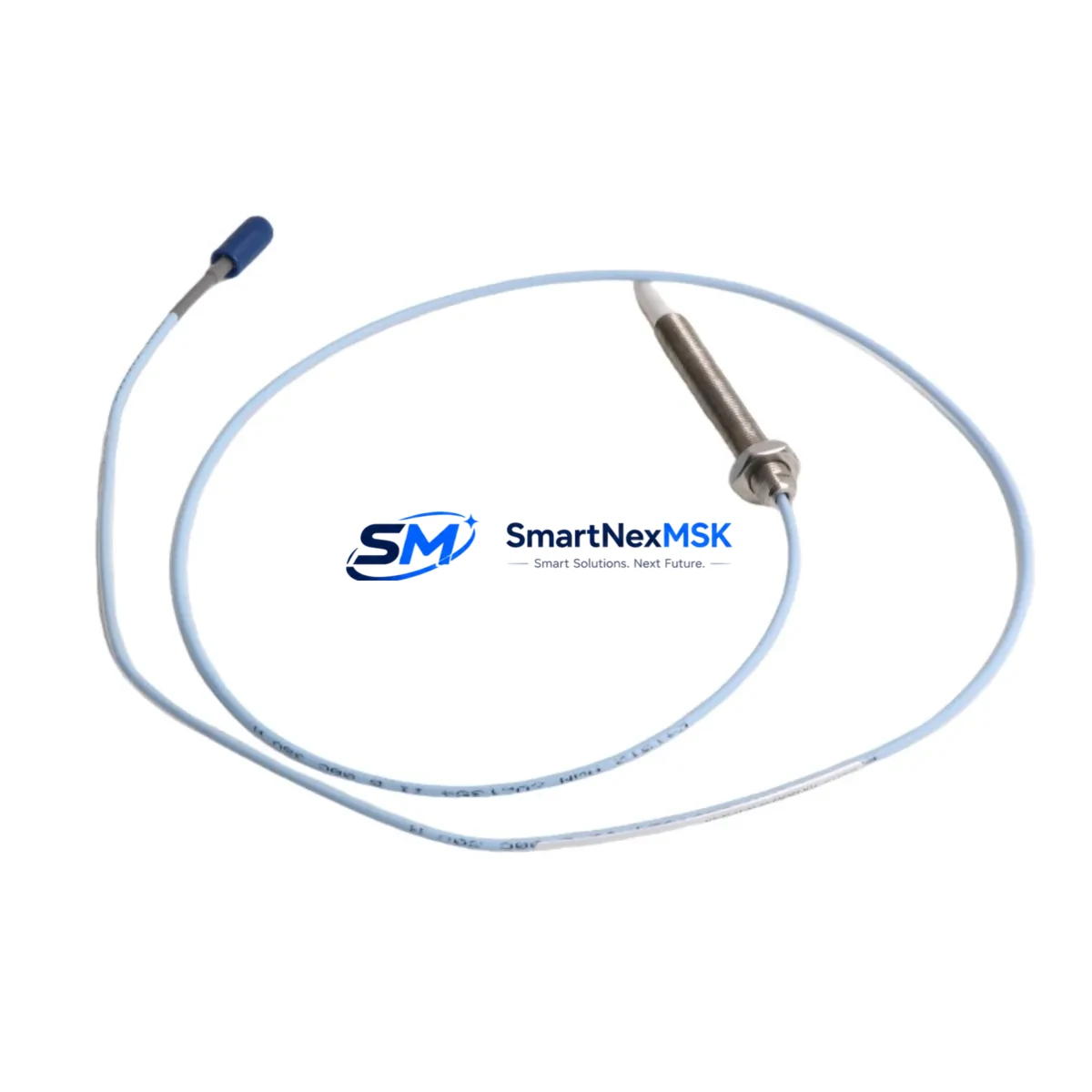
The Bently Nevada 330905-00-17-05-02-00 is an eddy-current proximity probe engineered for the 3300 NSv vibration monitoring system — one of the most widely deployed machinery protection platforms in rotating equipment facilities worldwide. Whether you are managing a planned outage, responding to an unplanned trip, or building a strategic spare parts inventory for critical turbomachinery, this probe delivers the dimensional accuracy, signal linearity, and environmental durability required for continuous, reliable operation.
Maintenance engineers and reliability teams operating compressors, steam turbines, gas turbines, pumps, and gearboxes depend on the 3300 NSv system to provide real-time shaft vibration, position, and speed data. A failed or degraded proximity probe is one of the most common causes of nuisance trips and false alarms in these systems. Stocking a verified replacement such as the 330905-00-17-05-02-00 eliminates the risk of extended downtime caused by long lead times on OEM procurement channels.
This unit ships fully tested, with documentation confirming electrical performance within OEM specification. A 12-month warranty is included from the date of shipment, covering manufacturing defects and functional failures under normal operating conditions.
Spare Maintenance Table
| Parameter | Specification |
|---|---|
| Part Number / SKU | 330905-00-17-05-02-00 |
| Brand | Bently Nevada |
| Series | 3300 NSv Vibration Monitoring System |
| Product Type | Eddy-Current Proximity Probe |
| Probe Length | 17 inches (432 mm) |
| Cable Length | 5 meters |
| Connector Type | Standard 3300 NSv system connector |
| Output Sensitivity | 200 mV/mil (7.87 V/mm) nominal |
| Operating Temperature | -35°C to +120°C (probe tip) |
| Application | Shaft radial vibration, axial position, speed measurement |
| Compatible Systems | Bently Nevada 3300 NSv, 3300 XL, 3500 series (with appropriate driver) |
| Installation | Threaded mounting, gap set to 1.0 mm (40 mil) nominal |
| Origin | United States |
| Warranty | 12 Months from shipment date |
| Condition | New / Surplus New — tested prior to shipment |
Maintenance Planning for Continuous Operation
When replacing the 330905-00-17-05-02-00 proximity probe in a 3300 NSv installation, a thorough site inspection of the surrounding measurement chain is essential to prevent repeat failures and ensure signal integrity. Maintenance engineers should treat probe replacement as an opportunity to audit the complete vibration monitoring loop.
Begin by inspecting the 3300 NSv extension cable (typically a 330130 series cable) that connects the probe to the proximitor. Cable jacket abrasion, connector corrosion, or shield continuity breaks are frequent contributors to signal noise and erratic readings. Replace the extension cable if any physical damage or impedance deviation is detected.
Next, verify the condition of the 3300 NSv proximitor/driver module (such as the 330180 or 330185 series). The proximitor converts the probe’s impedance change into a voltage signal; a drifting or failed proximitor will produce incorrect gap voltage even with a new probe installed. Confirm the proximitor output voltage at the nominal 1.0 mm gap falls within the -10.0 VDC to -18.0 VDC window specified for the 3300 NSv system.
Inspect the 3500/40M proximitor I/O module in the 3500 rack if the 3300 NSv probes feed into a 3500 series protection rack. Verify that the I/O module channel configuration matches the probe sensitivity and gap settings. A misconfigured channel will generate false alerts or suppress genuine alarms.
Check the 3500 rack power supply module (such as the 3500/15 or 3500/05) for output voltage stability. Fluctuating rack power is a known cause of intermittent probe signal dropout. If the power supply is approaching end-of-life or shows ripple on the DC bus, schedule replacement during the same maintenance window.
Review the Keyphasor module (3500/25 or equivalent) if the machine uses phase-referenced vibration analysis. The Keyphasor signal is critical for 1X and 2X vector analysis; a degraded Keyphasor probe or driver will corrupt all phase-referenced data across the rack.
For installations where the 3300 NSv system feeds a DCS historian or safety PLC via 4-20 mA or digital output, verify the signal isolator or conditioner module in the marshalling cabinet. Signal isolators can develop ground loops or offset errors over time, particularly in high-EMI environments near variable frequency drives.
Inspect terminal blocks and field wiring in the junction box and control cabinet. Loose terminations on the probe signal pair introduce noise that mimics mechanical vibration. Torque all terminals to specification and verify shield grounding at one end only.
Finally, if the machine includes a thrust position measurement channel, confirm that the axial probe (often a companion 330905 series unit on the thrust collar) and its driver are also within calibration. Axial and radial probes in the same measurement plane should be replaced or recalibrated together to maintain consistent protection coverage.
Site Replacement Workflow
Step 1 — Isolation and Lockout: Follow site LOTO procedures. Isolate the 3300 NSv rack channel associated with the probe being replaced to prevent spurious trips during installation. Most 3500 racks allow channel bypass via System 1 software or front-panel keyswitch.
Step 2 — Probe Removal: Unthread the existing 330905-00-17-05-02-00 probe from the mounting bracket. Note the existing gap (number of turns from flush) as a reference for the replacement unit. Inspect the probe tip and target area for contamination, scoring, or runout.
Step 3 — Cable Inspection: Disconnect the extension cable at both the probe and proximitor ends. Measure cable resistance and shield continuity. Replace if out of specification.
Step 4 — New Probe Installation: Thread the replacement 330905-00-17-05-02-00 into the bracket. Set the air gap to 1.0 mm (40 mil) using a feeler gauge or by monitoring the proximitor output voltage (target: -10.4 VDC ± 0.5 VDC at nominal gap). Lock the probe in position with the jam nut.
Step 5 — Signal Verification: Reconnect the extension cable and power the proximitor. Verify the DC gap voltage, confirm the channel is within the OK window in the 3500 rack display, and check for noise on the AC vibration signal with the machine at rest. Acceptable noise floor is typically below 0.5 mil pk-pk.
Step 6 — Return to Service: Remove the channel bypass, confirm alarm setpoints are active, and document the replacement in the CMMS. Update the spare parts inventory to trigger reorder of a replacement 330905-00-17-05-02-00 unit.
Spare Parts Support FAQ
Q1: Is the 330905-00-17-05-02-00 compatible with both the 3300 NSv and the 3500 series racks?
The 330905-00-17-05-02-00 probe is designed for the Bently Nevada 3300 NSv system. It can interface with 3500 series racks when used with the appropriate 3300 NSv proximitor and I/O module configured for the correct sensitivity. Always verify the channel configuration in the 3500 rack software before installation.
Q2: What is the recommended spare parts stocking strategy for critical rotating equipment?
For machinery classified as critical (single-train compressors, main turbines, boiler feed pumps), industry best practice recommends maintaining a minimum of two replacement probes per measurement plane on-site. For non-critical or standby equipment, one spare per machine train is typically sufficient. Probes should be stored in original packaging in a dry, temperature-controlled environment and inspected annually.
Q3: How is each unit tested before shipment?
Every 330905-00-17-05-02-00 unit is bench-tested prior to shipment using a calibrated 3300 NSv proximitor and a reference target. Gap voltage, sensitivity, and noise floor are verified against OEM specification. A test report is available upon request.
Q4: What does the 12-month warranty cover?
The 12-month warranty covers manufacturing defects and functional failures under normal operating conditions from the date of shipment. It does not cover damage resulting from improper installation, incorrect gap setting, mechanical impact, or operation outside the rated environmental envelope. Warranty claims are processed with return of the defective unit and a brief failure description.
© 2026 SMARTNEXMSK. All rights reserved.
Original Source: https://smartnexmsk.com
Contact: sales@smartnexmsk.com | +86 18259474341


