Bently Nevada 330905-00-17-10-02-00 3300 XL Retrofit Probe: Compatible Upgrade for Legacy Vibration Monitoring Systems
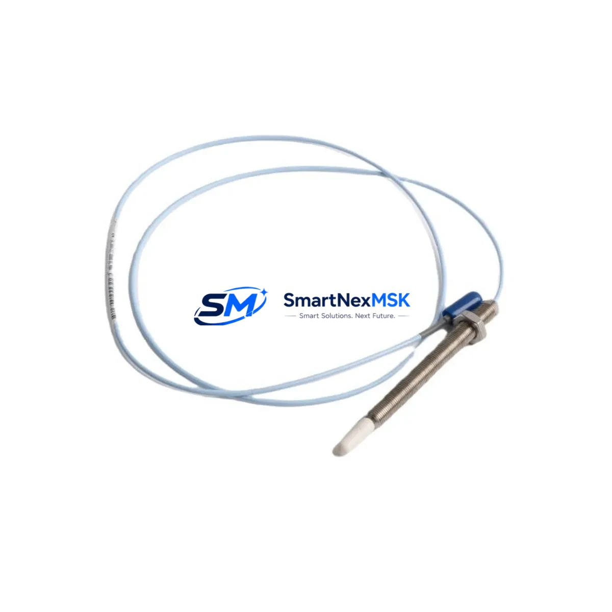
The Bently Nevada 330905-00-17-10-02-00 is an 8mm eddy-current proximity probe designed for the 3300 XL Series continuous vibration monitoring platform. This retrofit-ready unit serves as a direct drop-in replacement for aging or discontinued probes in rotating machinery protection systems, including steam turbines, gas compressors, centrifugal pumps, and large electric motors. Whether you are managing a planned control system upgrade or responding to an unplanned probe failure, this component is stocked and ready for immediate dispatch with a 12-month warranty.
Industrial facilities operating legacy Bently Nevada 3300 Series racks frequently encounter obsolescence challenges as original probe assemblies reach end-of-life. The 330905-00-17-10-02-00 addresses this directly by maintaining full electrical and mechanical compatibility with the 3300 XL proximitor/seismic monitor, the 3300/16 and 3300/20 rack-mount monitors, and associated barrier and junction box wiring. Replacement does not require reprogramming of the monitor module or recalibration of the gap voltage setpoints, provided the installation gap is set correctly during commissioning — typically between -10 VDC and -18 VDC for standard 8mm probes.
Upgrade Compatibility Table
| Parameter | Detail |
|---|---|
| SKU / Part Number | 330905-00-17-10-02-00 |
| Series Compatibility | Bently Nevada 3300 XL, 3300/16, 3300/20 |
| Probe Diameter | 8mm eddy-current |
| Cable Length | 5m (extension cable + probe cable assembly) |
| Connector Interface | Standard BNC / coaxial to proximitor input |
| Gap Voltage Range | -10 VDC to -18 VDC (nominal -12 VDC at 1.0mm gap) |
| Mounting Thread | M10 x 1.0 (standard 8mm probe thread) |
| Installation Requirement | Verify bracket clearance and target material (steel preferred) |
| Communication Compatibility | Analog 4–20 mA output via 3300 XL monitor; compatible with DCS/SCADA analog input cards |
| Replacement Recommendation | Direct drop-in for 330905 series; verify extension cable part number (330130 or 330180 series) |
| Commissioning Focus | Gap setting, polarity check, OK relay verification, and proximitor power supply confirmation |
| Warranty | 12 months from date of shipment |
Retrofit Planning for Existing Automation Systems
Replacing the 330905-00-17-10-02-00 in an operating plant requires a structured approach to avoid extended downtime and to protect the integrity of the existing vibration monitoring loop. Before removing the failed or aging probe, engineers should document the current gap voltage reading from the 3300 XL proximitor/seismic monitor front panel and record the OK relay status. This baseline ensures that the replacement probe is installed to the same mechanical gap and that the monitor’s OK relay resets correctly after installation.
In many retrofit scenarios, the probe is only one component in a larger assembly. The extension cable — typically a 330130-XX-XX or 330180-XX-XX series armored cable — should be inspected for jacket damage, connector corrosion, or shield continuity loss. If the extension cable shows degradation, it is advisable to replace it alongside the probe to avoid a repeat failure. The proximitor itself, such as the 3300 XL 8mm proximitor (part number 330180-X1-05 or similar), should also be tested for output linearity before the system is returned to service.
For facilities upgrading from older 3300 Series non-XL monitors to the current 3300 XL platform, the probe assembly remains compatible, but the monitor rack — including the 3300/16 or 3300/20 rack chassis — may require updated I/O termination boards. The 3300 XL monitor module accepts the same coaxial probe input but offers enhanced OK relay logic and improved EMI rejection. During this type of platform migration, it is common to also replace the power supply module within the rack, such as the 3300/05 power supply, to ensure stable -24 VDC proximitor excitation across all channels.
Where the vibration monitoring system feeds into a DCS or safety instrumented system (SIS), the 4–20 mA analog output from the 3300 XL monitor connects to the DCS analog input card. Engineers should verify that the DCS tag configuration — including engineering unit scaling, alarm setpoints, and trip logic — is preserved during the hardware swap. If the facility uses a System 1 Evolution condition monitoring software platform, the probe channel configuration in the software should be reviewed to confirm that the transducer sensitivity (mV/µm) and gap calibration curve remain aligned with the replacement probe’s specifications.
For plants operating multiple machines on a shared monitoring rack, it is good practice to perform the probe replacement during a scheduled maintenance window rather than a forced outage. Having a spare 330905-00-17-10-02-00 probe assembly on the shelf — along with a matched extension cable and a tested proximitor — allows the maintenance team to complete the swap within a single shift, minimizing exposure to unmonitored operation. Junction box terminal blocks and cable glands should also be inspected during the replacement to ensure IP65 or better ingress protection is maintained in outdoor or wash-down environments.
Downtime Control During System Migration
Minimizing downtime during a probe replacement or monitor upgrade begins with pre-staging all replacement components before the maintenance window opens. For the 330905-00-17-10-02-00, this means having the probe, extension cable, and any required mounting hardware — including the probe holder and locknut — ready at the work site. The 3300 XL monitor should remain powered during the swap if the machine can be safely isolated, allowing the OK relay status and gap voltage to be monitored in real time as the new probe is installed and adjusted.
Where the machine cannot be isolated, a temporary bypass of the OK relay output may be required to prevent a spurious trip during the gap-setting procedure. This bypass must be authorized under the facility’s management of change (MOC) process and removed immediately after commissioning is complete. The replacement probe should be gapped to the manufacturer’s recommended nominal gap — typically 1.0mm for 8mm probes — and the gap voltage confirmed at the proximitor output before the bypass is lifted.
For larger migration projects involving multiple probes across a turbine train — such as replacing both radial vibration probes, the axial thrust probe, and the Keyphasor probe (330980 series) simultaneously — a phased replacement plan reduces the risk of losing all monitoring channels at once. Each probe channel should be commissioned and verified independently before moving to the next. The Keyphasor signal, which provides the once-per-revolution reference for phase and speed measurements, is particularly critical and should be the last channel restored to service after all other probes are confirmed operational.
After all probes are installed and gapped, a full system functional test should be performed: verify OK relay outputs at the monitor, confirm 4–20 mA signal levels at the DCS input cards, check alarm and trip setpoints in the monitor configuration, and validate System 1 or equivalent software is receiving clean waveform data. Document the as-left gap voltages and OK relay states for the maintenance record before returning the machine to service.
Retrofit Support FAQ
Q1: Is the 330905-00-17-10-02-00 a direct replacement for older 330905 series probes?
Yes. The 330905-00-17-10-02-00 is electrically and mechanically compatible with other probes in the 330905 family. The suffix digits indicate cable length and connector configuration. Verify that the replacement probe’s cable length and connector type match your existing installation before ordering. If the extension cable part number differs, the probe can still be used with a compatible 330130 or 330180 series extension cable.
Q2: Do I need to recalibrate the 3300 XL monitor after replacing the probe?
In most cases, no full recalibration is required. The 3300 XL monitor stores its configuration in non-volatile memory. After installing the replacement probe, set the mechanical gap to achieve the nominal gap voltage (-12 VDC ± 1 VDC for 8mm probes), verify the OK relay resets, and confirm the vibration reading is within expected baseline range. If the monitor’s calibration has drifted or if the probe sensitivity differs from the original, a full channel calibration using a calibration fixture may be required.
Q3: What should I check during the pre-shipment inspection of a replacement probe?
Each 330905-00-17-10-02-00 unit shipped by SMARTNEXMSK undergoes a pre-shipment functional test including coil resistance measurement, insulation resistance check, and visual inspection of the probe tip, cable jacket, and connector. A test certificate is available on request. Upon receipt, inspect the probe tip for physical damage, verify the connector is clean and undamaged, and perform a bench gap test using a calibrated proximitor before installation.
Q4: What warranty coverage is provided?
All units carry a 12-month warranty from the date of shipment. The warranty covers manufacturing defects and functional failures under normal operating conditions. It does not cover damage resulting from incorrect installation, mechanical impact, or operation outside the specified gap voltage range. For warranty claims or technical support, contact sales@smartnexmsk.com or call +86 18259474341.
© 2026 SMARTNEXMSK. All rights reserved.
Original Source: https://smartnexmsk.com
Contact: sales@smartnexmsk.com | +86 18259474341


