Bently Nevada 330905-00-19-10-02-05 Retrofit-Ready Proximity Probe for 3300 NSv Control Systems
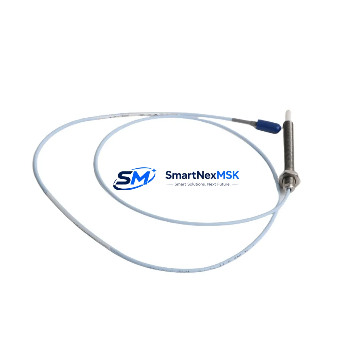
The Bently Nevada 330905-00-19-10-02-05 is an 8mm eddy current proximity probe engineered for seamless integration into existing 3300 NSv vibration monitoring systems. Designed with retrofit compatibility as a core requirement, this probe serves as a verified drop-in replacement for aging or discontinued units across rotating machinery protection platforms in oil & gas, power generation, petrochemical, and heavy industrial environments. Whether you are executing a planned control system upgrade, recovering from an unplanned shutdown, or sourcing a long-lead discontinued spare, the 330905-00-19-10-02-05 delivers the dimensional accuracy, signal linearity, and connector compatibility required to restore full system functionality with minimal downtime.
This probe is part of the Bently Nevada 3300 Series proximity transducer system, which includes the probe, extension cable, and proximitor sensor as a matched set. When replacing the 330905-00-19-10-02-05, engineers must confirm that the paired extension cable — typically a 330130 or 330180 series — and the proximitor sensor, such as the 3300 XL 8mm proximitor (330180-X1-05), are either retained from the existing installation or replaced as a matched assembly. Mismatched cable lengths or proximitor models will affect the output voltage range and gap calibration, leading to false alarms or missed trips in the machinery protection system.
Upgrade Compatibility Table
| Parameter | Detail |
|---|---|
| SKU / Part Number | 330905-00-19-10-02-05 |
| Probe Diameter | 8mm eddy current proximity probe |
| Compatible System | Bently Nevada 3300 NSv Machinery Protection System |
| Connector Type | Standard 3300 Series coaxial connector (MIL-C-17 compatible) |
| Cable Compatibility | 330130 / 330180 extension cable series (must match total system length) |
| Proximitor Compatibility | 3300 XL 8mm Proximitor Sensor (330180 series) |
| Installation Requirement | Matched probe + cable + proximitor assembly; gap voltage calibration required |
| Communication / Output | Analog voltage output (–24 VDC supply); integrates with 3500 rack I/O modules |
| Replacement Recommendation | Direct drop-in for same-series 330905 variants; verify cable length suffix |
| Commissioning Focus | Gap voltage setting, OK relay verification, Keyphasor® signal alignment |
| Warranty | 12-Month Warranty — covers manufacturing defects and functional performance |
Retrofit Planning for Existing Automation Systems
Retrofitting the 330905-00-19-10-02-05 into an operational plant environment requires a structured approach that accounts for the full transducer chain and the downstream monitoring rack. In most 3300 NSv installations, the proximity probe feeds signal through a 330130 extension cable into a 3300 XL proximitor, which in turn connects to a 3500/40M proximitor I/O module housed in a 3500 rack. Before removing the existing probe, technicians should document the current gap voltage reading — typically between –10 VDC and –18 VDC for an 8mm probe — and record the OK relay status on the 3500/20 rack power supply module to establish a baseline for post-installation verification.
When the plant’s machinery protection architecture includes a Keyphasor® module such as the 3500/25, the phase reference signal must be re-verified after probe replacement to ensure tachometer-based vector measurements remain accurate. In turbine and compressor applications where the 3500/42M four-channel dynamic pressure monitor or the 3500/44M aeroderivative turbine monitor is part of the rack, any change to the proximity transducer chain can affect alarm setpoints stored in the rack configuration. It is strongly recommended to export the rack configuration from System 1 software or the 3500 Rack Configuration Software before beginning the swap, preserving all channel setpoints, full-scale ranges, and alert/danger thresholds.
For installations where the 3300 NSv system is being migrated toward a newer 3500 Series architecture, the 330905-00-19-10-02-05 remains fully compatible as an interim probe during phased upgrades. This allows the plant to replace worn or out-of-tolerance probes on a rolling basis without committing to a full rack replacement in a single outage window. In parallel, engineers should audit the condition of the 330130 extension cables for jacket cracking, connector corrosion, or impedance drift — issues that are common in high-temperature or high-vibration environments and that can cause intermittent OK dropouts even with a new probe installed.
Where the control cabinet also houses a Bently Nevada 3300/55 dual-input monitor or legacy 3300/16 standard transient data interface, the probe replacement process should include a functional test of the monitor’s buffered output BNC connectors to confirm signal integrity before returning the machine to service. Plants running System 1 Evolution software can use the live trend display to confirm the gap voltage stabilizes within the calibrated linear range immediately after installation, providing real-time confidence before the machine is restarted.
Downtime Control During System Migration
Minimizing unplanned downtime during a proximity probe replacement begins with pre-staging the replacement 330905-00-19-10-02-05 and verifying its factory calibration certificate before the maintenance window opens. A pre-tested, serialized probe that has been bench-verified against a reference target reduces the risk of discovering a defective unit after the machine is already offline. SMARTNEXMSK ships each unit with a functional test report, and the 12-month warranty covers the full post-installation period, providing assurance that the replacement will perform to specification throughout the next planned maintenance interval.
During the swap, the original program logic in the 3500 rack does not require modification — the 330905-00-19-10-02-05 is a direct electrical and mechanical replacement that preserves all existing channel configurations, alarm setpoints, and OK relay wiring. The only field adjustment required is the physical gap setting, which should be performed with a calibrated gap tool and confirmed against the proximitor’s output voltage using a digital multimeter before the machine is brought back online. If the installation includes a 3500/22M transient data interface or a 3500/32 relay module, the relay output states should be verified in bypass mode before releasing the machine to normal operation to prevent spurious trips during the startup transient.
For plants where continuous operation is critical and a hot-standby arrangement is in place, the 330905-00-19-10-02-05 can be pre-installed in the redundant measurement path while the primary channel remains active, allowing gap calibration and signal verification to be completed without interrupting the protection function. This approach is particularly effective in API 670-compliant installations where dual-voting logic is configured in the 3500 rack, as the system will continue to provide full protection coverage on the active channel throughout the replacement procedure.
Retrofit Support FAQ
Q1: Is the 330905-00-19-10-02-05 a direct replacement for other 330905 suffix variants?
The 330905 base part number is common across the 3300 NSv 8mm probe family, with suffixes indicating cable length, connector type, and temperature rating. The -00-19-10-02-05 suffix specifies a 0.5m (19-inch) armored probe with standard temperature rating and a 5-pin connector configuration. Before substituting a different suffix variant, confirm that the total system cable length — probe plus extension cable — matches the proximitor’s calibrated range. Mismatched lengths will shift the linear output range and require recalibration of the proximitor.
Q2: What commissioning steps are required after installation?
After mechanical installation, set the probe gap to achieve a gap voltage of approximately –12 VDC (midpoint of the linear range) using a non-conductive gap tool. Verify the OK relay on the 3500/20 power supply module is energized, confirming the transducer chain is within the OK voltage window. Use System 1 or the 3500 Rack Configuration Software to confirm the channel is reading within the expected range before releasing the bypass. Document the as-left gap voltage and OK status in the plant’s maintenance management system.
Q3: Can this probe be used with legacy 3300 monitors that are not part of the 3500 rack?
Yes. The 330905-00-19-10-02-05 is electrically compatible with legacy 3300/16, 3300/55, and 3300/46 monitors that accept standard 3300 Series transducer inputs. The probe’s output characteristics — sensitivity, linear range, and OK window — are consistent across the 3300 monitor family. However, if the legacy monitor is being decommissioned as part of the upgrade, the probe can be retained and reconnected to a 3500/40M or 3500/42M I/O module in the new rack without modification.
Q4: What does the 12-month warranty cover, and how is it claimed?
The 12-month warranty covers manufacturing defects, connector integrity, and functional performance within the specified linear range. It does not cover damage resulting from incorrect gap setting, reverse polarity wiring, or installation in environments exceeding the probe’s rated temperature range. To initiate a warranty claim, contact SMARTNEXMSK with the unit serial number, installation date, and a description of the observed fault. Replacement units are dispatched within 3 business days of claim verification, and a functional test report is included with each replacement shipment.
© 2026 SMARTNEXMSK. All rights reserved.
Original Source: https://smartnexmsk.com
Contact: sales@smartnexmsk.com | +86 18259474341


