Bently Nevada 330905-00-21-10-02-00 Retrofit Proximity Probe for 3300 NSv Control Systems
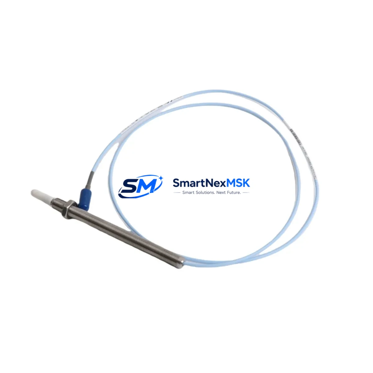
The Bently Nevada 330905-00-21-10-02-00 is an 8 mm eddy-current proximity probe engineered for continuous shaft vibration and position monitoring within the Bently Nevada 3300 NSv series. As legacy 3300 XL and earlier 3300 NSv installations approach end-of-service life, this probe serves as a verified drop-in retrofit component, enabling plant engineers to restore full vibration-monitoring capability without redesigning the existing rack architecture or replacing the entire monitoring chain.
Sourced from certified supply channels and subjected to pre-shipment functional testing, each unit ships with a 12-month warranty covering manufacturing defects and parametric drift. Global logistics support ensures delivery to refineries, power generation facilities, compressor stations, and rotating-equipment maintenance teams worldwide.
Upgrade Compatibility Table
| Parameter | Detail |
|---|---|
| SKU / Part Number | 330905-00-21-10-02-00 |
| Series Compatibility | Bently Nevada 3300 NSv, 3300 XL (with adapter verification) |
| Probe Diameter | 8 mm |
| Cable Length | 2.0 m integral cable (verify against existing conduit run) |
| Extension Cable Pairing | 330130-045-00-00 or 330130-080-00-00 (confirm total system length) |
| Driver / Proximitor | 3300 XL 8 mm Proximitor® Sensor (330180-X1-05) |
| Mounting Thread | M10 × 1 (confirm bracket thread before installation) |
| Gap Voltage Range | −10 VDC to −18 VDC (set to −12 VDC nominal at 1.0 mm gap) |
| Communication / Output | Analogue voltage signal; integrates with 3500/40M and 3500/42M monitor modules |
| Replacement Recommendation | Direct drop-in for worn or failed 330905-series probes; re-gap and re-calibrate after installation |
| Commissioning Focus | Gap voltage verification, sensitivity check (200 mV/mil), OK relay status confirmation |
| Warranty | 12 months from shipment date |
Retrofit Planning for Existing Automation Systems
A successful retrofit of the 330905-00-21-10-02-00 begins well before the maintenance window opens. Engineers should pull the existing rack drawing to confirm the 3300 NSv rack configuration — typically a 19-inch, four-slot or eight-slot chassis — and verify that the installed 3300 XL 8 mm Proximitor® Sensor (330180-X1-05) is still within calibration. If the Proximitor is also degraded, replacing both the probe and the Proximitor as a matched pair eliminates the risk of residual sensitivity error.
Next, audit the extension cable run. The 330130-045-00-00 (4.5 m) or 330130-080-00-00 (8.0 m) extension cables must be checked for insulation integrity and connector corrosion, particularly in high-humidity or high-vibration environments. Total system cable length — probe integral cable plus extension — must fall within the driver’s specified range; exceeding this introduces scale-factor error that the 3500/40M Proximitor Monitor cannot compensate for in software alone.
For plants running the Bently Nevada 3500 rack alongside the 3300 NSv system, confirm that the 3500/20 Rack Interface Module firmware is current, as older firmware versions may not correctly interpret the OK status relay from a newly installed probe during the first power-on cycle. Similarly, if the plant historian or DCS — such as a Honeywell Experion PKS or Emerson DeltaV node — is receiving vibration data via Modbus or OPC-DA from the 3500 rack, verify that the tag mapping and engineering-unit scaling remain intact after the probe swap. A mismatch in the EU range (typically 0–25 mil pp) will trigger spurious alarms on the HMI operator screen until the display block is re-scaled.
I/O wiring at the 3300 NSv terminal block should be documented with photographs before disconnection. The probe cable shield must be grounded at one end only — typically at the Proximitor housing — to prevent ground-loop interference that manifests as a 50 Hz or 60 Hz noise floor elevation on the vibration spectrum. After reconnection, use a Bently Nevada ADRE 408 DSPi or equivalent portable data collector to capture a baseline spectrum and compare it against the pre-replacement trend to confirm the new probe is tracking correctly.
Where the retrofit is part of a broader control-cabinet upgrade — for example, migrating from a standalone 3300 NSv rack to a fully integrated Bently Nevada System 1 software environment — the probe itself remains compatible, but the 3500/22M Transient Data Interface module may need to be added to the rack to support waveform capture and orbit plot generation in System 1. This is a common upgrade path for turbine and compressor trains where predictive maintenance programmes require full waveform data rather than overall vibration levels alone.
Downtime Control During System Migration
Minimising unplanned downtime during a proximity probe replacement requires a structured hot-swap protocol. Where the process permits a brief bypass, configure the 3500/40M monitor to inhibit the danger alarm on the affected channel before breaking the probe connection — this prevents a spurious machine trip during the swap interval. The inhibit state should be logged in the plant DCS and cleared immediately after the new probe is gapped and the OK relay has confirmed a healthy signal.
Preserve the original program logic in the 3500 rack by exporting the full rack configuration from Rack Configuration Software (RCS) before any hardware change. This file serves as the restore point if the replacement probe or Proximitor introduces an unexpected parameter shift. For plants using Bently Nevada System 1 Evolution, the asset configuration database should also be backed up, as probe serial-number changes may trigger a re-association prompt that, if dismissed incorrectly, can orphan historical trend data.
Field continuity is maintained by keeping the machine running on the remaining monitoring channels — radial vibration, axial position, and speed — while the affected channel is in inhibit. Once the 330905-00-21-10-02-00 is installed, gapped to −12 VDC, and the OK relay is confirmed green, the inhibit is lifted and the channel is returned to normal monitoring. Total intervention time for an experienced technician is typically 45–90 minutes per probe, excluding travel and permit-to-work administration.
Retrofit Support FAQ
Q1: Is the 330905-00-21-10-02-00 a direct replacement for all 330905-series probes?
The 330905-00-21-10-02-00 is a direct replacement for probes sharing the same 8 mm diameter, 2.0 m integral cable, and M10 × 1 mounting thread within the 330905 family. Variants with different cable lengths (e.g., 330905-00-21-10-05-00 with a 5.0 m cable) are not interchangeable without verifying total system cable length against the Proximitor specification. Always cross-reference the full part number before ordering.
Q2: What commissioning steps are required after installation?
After mechanical installation, set the probe gap to achieve a −12 VDC output (nominal 1.0 mm gap on steel target). Verify sensitivity at 200 mV/mil using a micrometer or gap-setting tool. Confirm the OK relay is energised and the 3500/40M channel shows a valid vibration reading within the expected baseline range. Document the as-found and as-left gap voltages in the maintenance management system.
Q3: Can the probe be used with a 3500 rack without a 3300 NSv Proximitor?
Yes — the 330905-00-21-10-02-00 probe is compatible with the 3500/40M Proximitor Monitor when paired with the correct 3300 XL 8 mm Proximitor Sensor (330180-X1-05). The 3500 rack provides the signal conditioning and alarm processing; the probe and Proximitor together form the complete measurement chain. Ensure the 3500/40M is configured for 8 mm probe type in RCS.
Q4: What does the 12-month warranty cover?
The warranty covers manufacturing defects, parametric drift beyond published specification, and connector or cable integrity failures under normal operating conditions. It does not cover damage resulting from incorrect installation gap, mechanical contact with the target, chemical exposure, or electrical overstress. Warranty claims are processed via sales@smartnexmsk.com with the original order reference and a brief fault description.
© 2026 SMARTNEXMSK. All rights reserved.
Original Source: https://smartnexmsk.com
Contact: sales@smartnexmsk.com | +86 18259474341


