Bently Nevada 330905-00-21-10-02-CN Retrofit-Ready Proximity Probe for 3300 NSv Control Systems
The Bently Nevada 330905-00-21-10-02-CN is a high-precision eddy-current proximity probe engineered for the 3300 NSv Series vibration monitoring platform. As legacy rotating machinery protection systems reach end-of-support cycles, plant engineers and reliability teams increasingly require a verified, drop-in replacement that preserves existing wiring topology, signal conditioning compatibility, and Bently Nevada System 1 software integration — without forcing a full rack redesign or extended shutdown window.
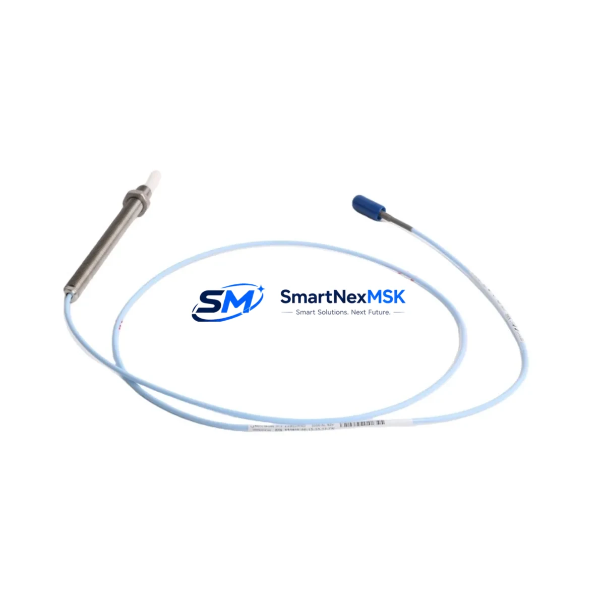
This retrofit-ready probe is manufactured to match the original 330905-00-21-10-02-CN dimensional envelope: 8 mm tip diameter, 5 m (standard) integral cable, -24 VDC bias voltage, and a sensitivity of 7.87 V/mm (200 mV/mil). It is fully compatible with the 3300 XL 8mm Extension Cable (330130-080-00-00) and the 3300 XL Proximitor Sensor (330180-X1-05), allowing field technicians to swap the probe without recalibrating the driver or modifying the junction box terminal strip.
For installations where the original probe interfaces with a 3500/42M Proximitor/Seismic Monitor or a 3500/40M Proximitor Monitor, the replacement unit maintains the same gap voltage curve, ensuring that existing OK relay setpoints and danger/alert thresholds remain valid after installation. No firmware update to the 3500 rack is required.
Upgrade Compatibility Table
| Parameter | OEM 330905-00-21-10-02-CN | Retrofit Replacement |
|---|---|---|
| Tip Diameter | 8 mm | 8 mm ✓ |
| Cable Length | 5 m integral | 5 m integral ✓ |
| Sensitivity | 7.87 V/mm (200 mV/mil) | 7.87 V/mm ✓ |
| Bias Voltage | -24 VDC | -24 VDC ✓ |
| Linear Range | 0.25–2.25 mm (10–90 mil) | 0.25–2.25 mm ✓ |
| Connector Type | Integral coaxial | Integral coaxial ✓ |
| Compatible Driver | 3300 XL Proximitor | 3300 XL Proximitor ✓ |
| Compatible Monitor | 3500/42M, 3500/40M | 3500/42M, 3500/40M ✓ |
| Communication Protocol | Analog (4–20 mA / voltage) | Analog ✓ |
| Installation Requirement | Standard probe mount, M10 thread | M10 thread ✓ |
| Warranty | OEM (EOL/discontinued) | 12-Month Warranty ✓ |
Retrofit Planning for Existing Automation Systems
Successful replacement of the 330905-00-21-10-02-CN within a live rotating machinery protection loop requires a structured pre-outage audit. Before the scheduled maintenance window, technicians should verify the existing 3300 XL Extension Cable condition and connector integrity — a degraded coaxial shield on the 330130-080-00-00 extension cable is a common source of signal noise that is often misattributed to the probe itself. If the extension cable shows continuity faults, it should be replaced concurrently with the probe to avoid a repeat outage.
At the junction box, confirm that the terminal strip wiring follows the standard three-wire configuration: shield drain, center conductor, and outer conductor. The 3300 NSv system uses a dedicated Proximitor power supply, typically the 3300/20 Power Supply module, which must be verified to deliver a stable -24 VDC rail within ±0.5 VDC tolerance before the new probe is energized. An out-of-tolerance supply will shift the gap voltage curve and trigger nuisance OK relay dropouts.
For plants running a 3500 Series protection rack, the 3500/42M Proximitor/Seismic Monitor card should be inspected for firmware revision compatibility. While the replacement probe does not require a firmware change, plants that have deferred rack firmware updates may encounter configuration mismatches when using the 3500 Rack Configuration Software (RCS) to verify channel assignments. It is advisable to export the existing rack configuration file before any hardware swap.
In multi-machine trains where the 330905-00-21-10-02-CN monitors a compressor or turbine shaft, the replacement sequence should account for the 3500/01 Rack Interface Module (RIM) communication link to the plant DCS or System 1 condition monitoring platform. Confirm that the Modbus or OPC-DA tag mapping for the affected channel remains intact after the probe swap, and perform a live gap voltage check (target: -10.0 VDC ±0.5 VDC at nominal air gap) before returning the machine to service.
Where I/O expansion is part of the modernization scope, plants migrating from a legacy 3300 rack to a 3500/22M Transient Data Interface or adding a 3500/64M Process Variable Monitor should plan the probe replacement as part of the broader rack upgrade, since both activities require the same machine outage window. Combining the probe swap with a 3500 rack I/O expansion eliminates a second planned shutdown and reduces total lifecycle cost.
Downtime Control During System Migration
Minimizing unplanned downtime during a proximity probe replacement begins with a pre-staged spare kit. Before the outage window opens, the replacement 330905-00-21-10-02-CN unit should be bench-tested using a portable Proximitor driver and a calibrated gap simulator to confirm sensitivity and OK relay output. This pre-verification step — which takes approximately 20 minutes — eliminates the risk of installing a defective spare and discovering the fault only after the machine is back online.
During the physical swap, the original probe mounting thread (M10 × 1.0) should be cleaned and inspected for galling before the replacement is installed. Torque the probe to the manufacturer-specified value and record the installed gap voltage using a calibrated digital multimeter at the Proximitor output terminals. Document the as-found and as-left gap voltages in the maintenance management system to establish a baseline for future trend analysis.
To protect existing program logic, do not modify any 3500 rack channel configuration parameters during the probe swap unless a configuration change is explicitly required by the upgrade scope. The replacement probe is designed to be transparent to the upstream monitoring system: the 3500/42M card, the System 1 software historian, and any HMI faceplate displays configured for the affected machine train will continue to function without modification. Alert and danger setpoints, OK relay logic, and Modbus register assignments remain unchanged.
For plants where continuous process control is critical, a temporary bypass relay can be installed on the OK relay output of the affected 3500/42M channel during the swap window, preventing a spurious machine trip. Remove the bypass immediately after the as-left gap voltage is confirmed within the linear range and the OK relay has re-energized. Log the bypass installation and removal times in the shift handover record.
Retrofit Support FAQ
Q1: Is the 330905-00-21-10-02-CN replacement a direct drop-in for the original Bently Nevada part?
Yes. The replacement unit matches the OEM dimensional envelope, sensitivity specification, bias voltage requirement, and connector type. No modifications to the existing extension cable, junction box wiring, or Proximitor driver are required for a standard swap.
Q2: What commissioning checks are required after installation?
After physical installation, measure the gap voltage at the Proximitor output terminals with the machine at rest. The target value is -10.0 VDC ±0.5 VDC at the nominal air gap specified in the original machine documentation. Verify that the OK relay has energized and that the System 1 or DCS channel is reading a valid vibration value before releasing the machine to operations.
Q3: How is wiring compatibility confirmed before ordering?
Confirm the existing extension cable part number (typically 330130-080-00-00 for a 5 m extension) and the Proximitor driver model (3300 XL or equivalent). The replacement probe is compatible with all standard 3300 NSv Series drivers. If the existing installation uses a non-standard cable length or a third-party driver, contact our technical team with the full system configuration before ordering.
Q4: What does the 12-month warranty cover?
The 12-month warranty covers manufacturing defects in materials and workmanship under normal operating conditions. Each unit undergoes pre-shipment functional testing including sensitivity verification, OK relay output check, and coaxial cable continuity test. A test report is available upon request. Warranty claims are processed within 5 business days of receipt of the returned unit.
© 2026 SMARTNEXMSK. All rights reserved.
Original Source: https://smartnexmsk.com
Contact: sales@smartnexmsk.com | +86 18259474341


