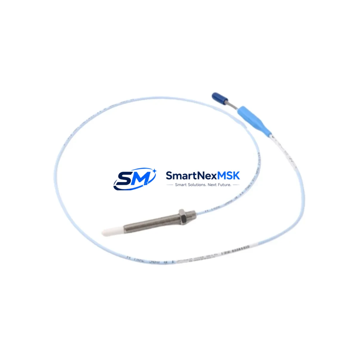
Bently Nevada 330908-00-30-10-01-05 Retrofit-Ready Proximity Probe for 3300 XL Control Systems
The Bently Nevada 330908-00-30-10-01-05 is an NSv Series 8mm eddy-current proximity probe engineered for continuous shaft vibration and position monitoring in rotating machinery. As legacy 3300 XL system installations age and original spare inventories are depleted, this probe serves as a verified retrofit-ready replacement that maintains full signal compatibility with existing Bently Nevada monitor racks, extension cables, and proximitor drivers — without requiring reprogramming of the control system or reconfiguration of the HMI display screens.
Industrial facilities operating gas turbines, steam turbines, compressors, pumps, and gearboxes frequently encounter the challenge of sourcing discontinued or long-lead-time proximity probes during unplanned shutdowns. The 330908-00-30-10-01-05 addresses this directly: it ships from verified stock, undergoes pre-shipment functional testing, and is backed by a 12-month warranty covering manufacturing defects and signal output integrity.
Upgrade Compatibility Table
| Parameter | 330908-00-30-10-01-05 (This Unit) | Retrofit Notes |
|---|---|---|
| Probe Series | NSv 8mm Eddy-Current | Compatible with 3300 XL monitor racks |
| Cable Length | 30 cm (integral) | Pair with 330130 or 330180 extension cables |
| Connector Type | NSv Standard | Direct mating with existing proximitor drivers |
| Proximitor Compatibility | 3300 XL 8mm Proximitor (e.g. 3300/16) | No driver replacement required |
| Installation Thread | M10 x 1.0 | Verify bracket thread before installation |
| Gap Voltage Range | −10 VDC nominal at 1.0 mm gap | Re-gap to spec after installation |
| Communication / Signal | Analog (−24 VDC supply) | No protocol migration required |
| Replacement Scope | Drop-in for discontinued 330908 variants | Confirm full part number suffix match |
| Commissioning Requirement | Gap setting + signal verification | Use Bently Nevada gap tool or equivalent |
| Warranty | 12-Month Warranty — manufacturing defects and signal output integrity | |
Retrofit Planning for Existing Automation Systems
A successful retrofit of the 330908-00-30-10-01-05 into an operating plant begins well before the probe reaches the field. Engineering teams should first audit the existing 3300 XL monitor rack configuration, confirming the installed proximitor driver model — typically a 3300/16 Proximitor or 3300/20 Proximitor — and verifying that the rack’s power supply module (such as the 3300/05 Power Supply) is delivering stable −24 VDC to the probe circuit. Voltage sag or ripple at the supply rail is a common root cause of false vibration alarms during probe changeovers and should be measured before the new probe is installed.
Extension cable continuity is the next critical checkpoint. The 330130-080-00-00 or 330180-X0-05 armored extension cables commonly used in turbine pedestals and compressor skids must be inspected for shield integrity and connector pin condition. A damaged extension cable will corrupt the gap voltage reading and cause the replacement probe to appear faulty even when it is functioning correctly. Replace any extension cable showing insulation cracking, connector corrosion, or continuity loss before commissioning the new probe.
For facilities migrating from older 7200 Series or 3000 Series monitor architectures to the 3300 XL platform, the 330908-00-30-10-01-05 is a natural fit within the upgraded rack. The NSv probe system eliminates the need for separate proximitor enclosures used in earlier generations, reducing panel space requirements and simplifying the wiring layout inside the control cabinet. During this type of platform migration, it is common to simultaneously upgrade the 3500/42M Proximitor I/O Module and reconfigure the 3500/22M Transient Data Interface to accept the new channel assignments — both of which are compatible with the NSv probe signal standard.
HMI screen updates are often overlooked during probe replacements. If the plant’s System 1 Evolution condition monitoring software or a third-party SCADA platform is configured with channel-specific tag names tied to the old probe serial number or calibration curve, those tags must be updated to reflect the new probe’s gap calibration constants. Failure to update the HMI configuration can result in incorrect vibration trend data being logged even when the physical installation is correct.
I/O expansion scenarios — such as adding a new measurement point to an existing rack — may require installing an additional 3500/40M Proximitor I/O Module alongside the new probe. Rack slot availability, backplane address assignment, and rack configuration software (Rack Configuration Software, RCS) settings should all be confirmed before the outage window begins to avoid delays during the installation phase.
Downtime Control During System Migration
Minimizing unplanned downtime during a proximity probe replacement requires a structured pre-outage preparation protocol. Before the machine is taken offline, the maintenance team should document the existing gap voltage reading at the installed probe location — typically between −9.5 VDC and −10.5 VDC for a correctly gapped 8mm NSv probe — and record this value as the baseline for post-installation verification. This baseline protects the original program logic in the 3300 XL monitor from being inadvertently altered during the swap.
The replacement probe, extension cable, and any required mounting hardware should be staged and pre-inspected before the outage begins. Pre-shipment testing performed on the 330908-00-30-10-01-05 confirms that the probe’s output sensitivity and linearity are within Bently Nevada factory specifications, reducing the risk of a failed commissioning test during the outage window. Once installed, the gap is set using a calibrated gap tool, the proximitor output is verified with a digital voltmeter, and the monitor rack’s OK relay status is confirmed before the machine is returned to service.
For facilities with redundant measurement channels — common on critical turbine trains where both radial vibration probes (X and Y planes) are monitored — it is advisable to replace both probes simultaneously during a planned outage rather than replacing them individually during separate unplanned events. This approach ensures matched calibration characteristics between the two channels and eliminates the risk of a second unplanned outage shortly after the first.
Retrofit Support FAQ
Q1: Is the 330908-00-30-10-01-05 a direct drop-in replacement for other 330908 suffix variants?
The 330908 base part number covers multiple cable length and connector configurations. The suffix -00-30-10-01-05 specifies a 30 cm integral cable, standard NSv connector, and specific temperature rating. Before ordering, confirm that the suffix on the installed probe matches this unit exactly. If the installed probe has a different cable length suffix (e.g., -00-50 or -00-100), a different variant will be required.
Q2: What commissioning steps are required after installation?
After mechanical installation, set the probe gap to achieve a gap voltage of approximately −10.0 VDC (±0.5 VDC) using the proximitor’s output terminals as the measurement point. Verify the monitor rack’s OK relay closes and that the vibration channel reads a stable baseline value consistent with the machine’s normal operating condition. Update any HMI or condition monitoring software tags if the probe serial number or calibration data has changed.
Q3: Does this probe require any wiring changes to the existing terminal block or junction box?
No wiring changes are required if the existing extension cable and proximitor driver are compatible with the NSv probe standard. The probe connects to the extension cable using the standard NSv push-on connector. If the existing extension cable uses an older connector style from a 7200 Series installation, an adapter or cable replacement will be necessary.
Q4: What does the 12-month warranty cover?
The 12-month warranty covers manufacturing defects, signal output integrity, and connector reliability under normal operating conditions. Each unit undergoes pre-shipment functional testing before dispatch. Warranty claims are supported by SMARTNEXMSK’s technical team — contact sales@smartnexmsk.com with the order reference and a description of the observed fault.
© 2026 SMARTNEXMSK. All rights reserved.
Original Source: https://smartnexmsk.com
Contact: sales@smartnexmsk.com | +86 18259474341


