Bently Nevada 330910-00-04-50-02-00 3300 XL NSv Spare: Spare Replacement & Industrial Downtime Risk Control
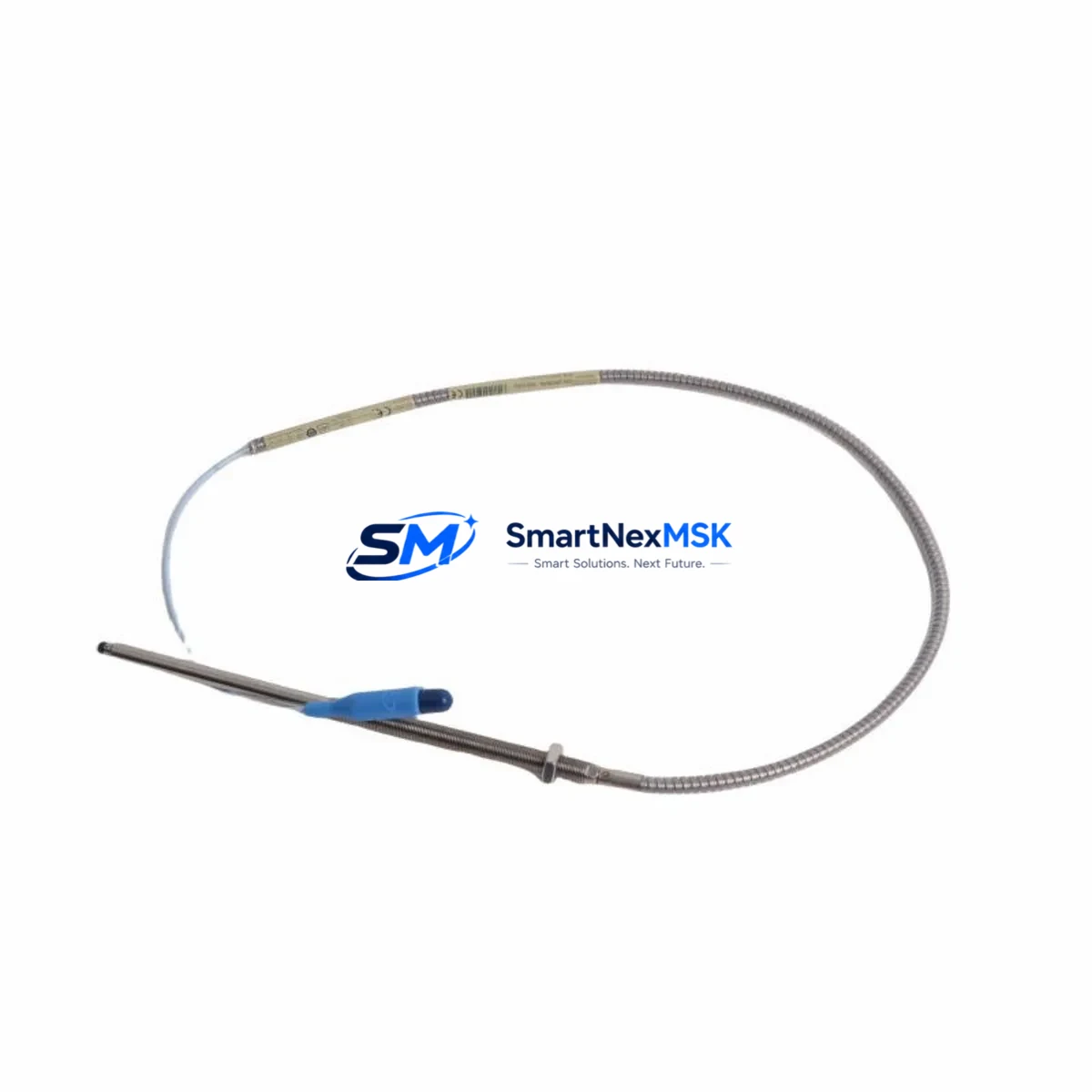
The Bently Nevada 330910-00-04-50-02-00 is an original eddy-current proximity transducer engineered for the 3300 XL NSv series vibration monitoring system. In rotating machinery protection environments — turbines, compressors, pumps, and gearboxes — this transducer is a critical front-line sensing element. When it fails or degrades, the entire vibration channel goes blind, exposing the machine to undetected shaft displacement, bearing wear, and catastrophic mechanical failure. Stocking a verified replacement is not optional; it is a fundamental requirement of any serious predictive maintenance program.
This listing provides a maintenance-ready, original-specification spare for immediate deployment. Each unit is inspected, function-tested, and shipped with full documentation. A 12-month warranty covers manufacturing defects and performance conformance to Bently Nevada factory specifications.
Spare Maintenance Table
| Parameter | Specification |
|---|---|
| Part Number | 330910-00-04-50-02-00 |
| Brand | Bently Nevada |
| Series | 3300 XL NSv |
| Type | Eddy-Current Proximity Transducer |
| Sensing Range | 0–50 mil (0–1.27 mm) linear range |
| Cable Length | 5 m (standard extension cable) |
| Output | –200 mV/mil (–7.87 V/mm) nominal |
| Supply Voltage | –24 VDC (via proximitor/driver) |
| Thread | M10 × 1 (standard mounting) |
| Compatibility | 3300 XL NSv Proximitor, 3300 XL 8mm System |
| Application Environment | Turbines, compressors, pumps, gearboxes |
| Origin | USA |
| Warranty | 12 Months |
| Condition | Original, new or reconditioned-to-spec |
| Shipping | Tested before dispatch, DHL/FedEx express available |
Maintenance Planning for Continuous Operation
Replacing the 330910-00-04-50-02-00 transducer in the field is rarely an isolated task. A disciplined maintenance engineer will treat this replacement as a trigger for a broader inspection of the entire vibration monitoring loop and the surrounding control cabinet. The transducer works in a matched system with the Bently Nevada 330130 proximitor/driver, which conditions the raw eddy-current signal into a usable –24 VDC output. If the transducer has failed due to cable damage, contamination, or mechanical impact, the proximitor should be bench-tested simultaneously — a degraded proximitor will cause a new transducer to read incorrectly from day one.
The extension cable (330130-045-00-CN or equivalent 3300 XL series cable) is the most frequently overlooked component. Connector corrosion, jacket cracking near the probe tip, and shield continuity breaks are common failure modes in high-vibration, high-temperature environments. Replace or megger-test the cable whenever the transducer is changed.
At the rack level, inspect the 3300/16 or 3300/20 monitor card that receives the proximitor output. Check the OK relay output, the gap voltage reading (should be –10 V ± 1 V at mid-gap), and the channel OK LED. A monitor card with a drifting input impedance will reject an otherwise healthy transducer signal. While the rack is open, verify the 3300 power supply module — typically a redundant –24 VDC rail — for output ripple and voltage stability under load.
For plants running older Bently Nevada 7200 series or 3500 series racks alongside 3300 XL NSv systems, confirm that the replacement transducer’s sensitivity and gap range are compatible with the specific monitor card firmware version. Mixed-generation systems are common in brownfield facilities, and a 3300 XL NSv transducer installed into a legacy 7200 rack without a sensitivity adapter will produce erroneous readings.
During the same maintenance window, inspect the terminal strip and field wiring in the junction box. Loose terminations on the signal pair (SIG and COM) are a leading cause of intermittent OK faults that are misdiagnosed as transducer failures. Check torque on all terminals and verify shield grounding at one end only. If the plant uses signal isolators or galvanic isolators between the proximitor and the DCS input card, test the isolator’s output linearity — a saturated isolator will clip the vibration signal and mask high-amplitude events.
Finally, if the machine is a critical asset on a continuous process line, consider stocking a second 330910-00-04-50-02-00 as a cold spare alongside a spare proximitor and a pre-terminated extension cable assembly. This three-component spare kit allows a complete channel swap in under 30 minutes, minimizing mean time to repair (MTTR) and reducing the risk of extended unplanned downtime.
Site Replacement Workflow
Step 1 — Isolation and permit: Obtain a hot-work or cold-work permit as required. Confirm the machine is in a safe state for transducer access. Do not remove the transducer from a running machine unless the monitor channel has been bypassed and the operations team has been notified.
Step 2 — Gap measurement before removal: Record the existing gap voltage from the monitor front panel or DCS historian. This baseline confirms whether the old transducer was reading correctly before failure and helps set the new transducer gap accurately.
Step 3 — Remove old transducer: Disconnect the extension cable at the junction box first. Unscrew the transducer from the bracket using the correct spanner — avoid gripping the cable. Inspect the bracket bore for wear, scoring, or contamination.
Step 4 — Install replacement 330910-00-04-50-02-00: Thread the new transducer in by hand until it contacts the shaft, then back off to achieve the target gap (typically 50 mil / 1.27 mm for mid-range operation). Lock with the jam nut. Reconnect the extension cable and verify connector seating.
Step 5 — Verify gap voltage: Power the proximitor and confirm gap voltage is within the –10 V ± 1 V acceptance window. Adjust gap as needed. Confirm the monitor channel shows OK status and the vibration reading is within expected baseline for the machine at rest.
Step 6 — Return to service and document: Remove the bypass, notify operations, and log the replacement in the CMMS with the new transducer serial number, installation date, and gap voltage. Schedule the next inspection interval per the plant’s predictive maintenance plan.
Spare Parts Support FAQ
Q: Is the 330910-00-04-50-02-00 compatible with both 3300 XL NSv and standard 3300 XL 8mm systems?
A: Yes. The 330910-00-04-50-02-00 is designed for the 3300 XL NSv matched system but is dimensionally and electrically compatible with standard 3300 XL 8mm proximitor/driver configurations. Always confirm the proximitor model number before installation to ensure the sensitivity calibration matches.
Q: What is included in the 12-month warranty and how is it claimed?
A: The 12-month warranty covers manufacturing defects and performance non-conformance to Bently Nevada factory specifications from the date of shipment. To claim, contact sales@smartnexmsk.com with the order number, installation date, and a description of the fault. We will arrange return shipping and provide a replacement or full refund.
Q: How is the unit tested before shipment?
A: Each 330910-00-04-50-02-00 unit is bench-tested for coil resistance, insulation integrity, and output sensitivity using a calibrated test rig before dispatch. A test report is available on request. Units that do not meet specification are quarantined and not shipped.
Q: What is the recommended spare inventory strategy for critical rotating machinery?
A: For critical assets (Category A machines), we recommend a minimum of two transducers per monitored shaft, one spare proximitor, and one pre-terminated extension cable per machine train. For Category B machines, one transducer and one proximitor per system is a practical minimum. Review your spare parts list annually against machine criticality and lead time.
© 2026 SMARTNEXMSK. All rights reserved.
Original Source: https://smartnexmsk.com
Contact: sales@smartnexmsk.com | +86 18259474341


