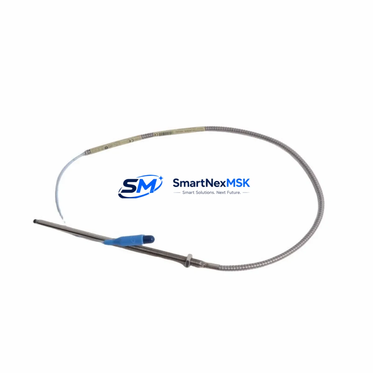
Bently Nevada 330910-00-06-50-02-00 3300 XL NSv Retrofit-Ready Proximity Transducer for Legacy Control Systems
The Bently Nevada 330910-00-06-50-02-00 is a high-precision eddy-current proximity transducer engineered for the 3300 XL NSv series monitoring platform. Designed for continuous vibration, position, and speed measurement in rotating machinery, this transducer is a direct retrofit-ready replacement for aging or discontinued units across turbine, compressor, pump, and motor protection systems. Whether you are upgrading an existing 3300 series installation, recovering from an unplanned failure, or executing a planned control system modernization, the 330910-00-06-50-02-00 delivers verified electrical and mechanical compatibility with minimal re-engineering effort.
This unit operates within the standard Bently Nevada 3300 XL NSv signal chain, interfacing directly with the 3300 XL 8mm Extension Cable assemblies and the dedicated 3300 XL Proximitor Sensor. The transducer outputs a linear DC voltage proportional to the gap between the probe tip and the observed target surface, making it fully compatible with existing 3500 Series Monitoring System rack cards, including the 3500/40M Proximitor/Seismic Monitor and the 3500/42M Proximitor/Seismic Monitor. Engineers migrating from earlier 7200 Series or standard 3300 Series installations will find that the NSv (Non-Standard Voltage) output range aligns with updated rack card input specifications, reducing the need for signal conditioning hardware during the transition.
Upgrade Compatibility Table
| Parameter | Details |
|---|---|
| SKU / Part Number | 330910-00-06-50-02-00 |
| Series | Bently Nevada 3300 XL NSv |
| Transducer Type | Eddy-Current Proximity Transducer |
| Tip Diameter | 8 mm |
| Cable Length | 0.6 m (integral cable) |
| Extension Cable Compatibility | 3300 XL 5m / 9m Extension Cable |
| Proximitor Compatibility | 3300 XL Proximitor Sensor (NSv output) |
| Rack / Monitor Compatibility | 3500/40M, 3500/42M, 3500 Series Rack |
| Replaces / Supersedes | 3300 Standard Series, 7200 Series proximity probes (with Proximitor swap) |
| Mounting Thread | M10 x 1 mm |
| Installation Requirement | Verify gap voltage at commissioning (typically −10 VDC ± 0.5 V at nominal gap) |
| Communication Protocol | Analog DC voltage (4–20 mA loop or direct rack input) |
| Commissioning Focus | Gap setting, polarity check, cable continuity, Proximitor output verification |
| Warranty | 12 Months from date of shipment |
Retrofit Planning for Existing Automation Systems
Successful deployment of the 330910-00-06-50-02-00 in a retrofit scenario requires systematic pre-installation planning. Begin by auditing the existing probe-and-extension-cable assembly. If the installed extension cable is a legacy 3300 Standard (non-XL) type, it must be replaced with a compatible 3300 XL Extension Cable to maintain the calibrated system sensitivity of 7.87 V/mm. Mixing XL and non-XL components will produce calibration errors that cannot be corrected at the rack level alone.
Next, verify the Proximitor Sensor model. The NSv designation on the 330910-00-06-50-02-00 requires a matching 3300 XL Proximitor Sensor configured for NSv output. If the existing Proximitor is a standard-voltage unit, it must be replaced concurrently. In many brownfield installations, the Proximitor is mounted inside the control cabinet on a dedicated DIN rail bracket or within the 3500 Series Rack enclosure itself — confirm physical access and available cabinet space before ordering replacement hardware.
For installations integrated with a GE / Bently Nevada System 1 condition monitoring platform, confirm that the transducer channel configuration in System 1 software reflects the NSv sensitivity curve. Incorrect sensitivity settings will cause the 3500/40M or 3500/42M monitor card to generate spurious alerts or fail the self-test routine. Update the channel database before bringing the new transducer online.
Where the machinery protection system feeds into a DCS or PLC — such as a Rockwell Automation ControlLogix rack or a Honeywell Experion PKS controller — verify that the 4–20 mA or hardwired trip relay outputs from the 3500 Series Rack remain correctly mapped to the DCS I/O module after the transducer swap. A change in Proximitor gain or output range can shift the 4–20 mA span, requiring re-scaling of the analog input card in the DCS. This step is frequently overlooked and is a common source of nuisance trips during post-retrofit commissioning.
If the machinery train includes a Keyphasor transducer — typically a 3300 XL 8mm Keyphasor Transducer mounted on the shaft — confirm that the Keyphasor channel in the 3500 rack is unaffected by the proximity probe replacement. The Keyphasor signal is used for phase reference in vibration analysis and must remain stable throughout the retrofit window. Similarly, if the system includes a 3500/15 Power Supply module or a 3500/20 Rack Interface Module, verify that the rack power budget accommodates any additional current draw from the new Proximitor Sensor.
For HMI integration, update the operator display faceplate in the SCADA or DCS HMI — whether running on a Wonderware InTouch, FactoryTalk View SE, or Honeywell Experion station — to reflect the correct engineering units, alarm setpoints, and tag descriptions associated with the replacement transducer channel. Failure to update HMI tag scaling is a leading cause of operator confusion during the first weeks of post-retrofit operation.
Downtime Control During System Migration
Minimizing unplanned downtime during a proximity transducer replacement requires a structured hot-swap or planned-outage strategy. For non-critical auxiliary machinery, a brief planned outage of 2–4 hours is typically sufficient to complete the physical swap, re-gap the transducer, verify Proximitor output, and confirm rack self-test passage. For critical turbine or compressor trains where continuous operation is required, coordinate the replacement with the next scheduled maintenance window and prepare a pre-staged, pre-tested replacement assembly — probe, extension cable, and Proximitor — to reduce on-site installation time to under 60 minutes.
Before removing the existing transducer, document the current gap voltage reading from the 3500 rack display or System 1 software. This baseline value serves as the acceptance criterion for the replacement unit. After installing the 330910-00-06-50-02-00 and its associated 3300 XL Extension Cable, adjust the transducer mounting depth until the Proximitor output matches the documented baseline within ±0.2 VDC. Lock the transducer in position with the jam nut and re-verify the gap voltage after tightening to account for any thread-induced rotation of the probe body.
Preserve the original PLC or DCS program logic throughout the migration. Do not modify ladder logic, function block diagrams, or structured text routines associated with the machinery protection interlock unless a deliberate logic upgrade is part of the project scope. Retaining the original program logic eliminates the risk of introducing new faults during the transducer replacement and allows the control system to resume normal operation immediately after the hardware swap is confirmed.
All replacement units shipped by SMARTNEXMSK are bench-tested prior to dispatch. Each 330910-00-06-50-02-00 unit is verified for tip resistance, cable continuity, and Proximitor compatibility before packaging, reducing the probability of a DOA unit reaching the field and extending an unplanned outage.
Retrofit Support FAQ
Q1: Is the 330910-00-06-50-02-00 a direct drop-in replacement for the standard 3300 8mm proximity probe?
A: The 330910-00-06-50-02-00 is a 3300 XL NSv series unit and is not directly interchangeable with standard 3300 (non-XL) probes without also replacing the extension cable and Proximitor Sensor. The XL system uses a different calibrated sensitivity and connector standard. A complete system swap — probe, extension cable, and Proximitor — is required for a correct retrofit.
Q2: What commissioning checks are required after installation?
A: After physical installation, verify the gap voltage at the nominal air gap (typically −10 VDC ± 0.5 V), confirm cable continuity end-to-end, check the Proximitor power supply voltage (typically −24 VDC), run the 3500 rack self-test, and confirm that all alarm and danger setpoints are active and correctly scaled in both the rack and the DCS/HMI.
Q3: Can this transducer be used with a Rockwell or Siemens PLC-based protection system instead of the 3500 rack?
A: Yes, provided the PLC analog input module accepts the DC voltage output range of the 3300 XL NSv Proximitor Sensor. The Proximitor outputs a standard DC voltage signal that can be wired to any analog input card with a compatible input range. Confirm the input impedance and voltage range of the PLC I/O module — such as a Rockwell 1756-IF16 or Siemens SM 331 — before finalizing the wiring design.
Q4: What does the 12-month warranty cover?
A: The 12-month warranty covers manufacturing defects, electrical failures under normal operating conditions, and DOA units. It does not cover damage resulting from incorrect installation, over-range electrical input, mechanical impact, or operation outside the specified environmental limits. Warranty claims are processed within 5 business days of receipt of the returned unit at our facility.
© 2026 SMARTNEXMSK. All rights reserved.
Original Source: https://smartnexmsk.com
Contact: sales@smartnexmsk.com | +86 18259474341


