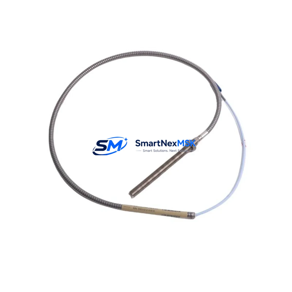
Bently Nevada 330910-00-08-10-02-CN Maintenance-Ready Spare 3300 NSv
The Bently Nevada 330910-00-08-10-02-CN is an original 8mm eddy-current proximity probe engineered for the 3300 NSv (Non-contact Vibration) measurement system. In rotating machinery protection applications — turbines, compressors, pumps, and gearboxes — this probe is the primary sensing element for radial shaft vibration, axial position, and differential expansion monitoring. When this component degrades or fails, the entire vibration monitoring loop is compromised, exposing critical rotating assets to undetected mechanical faults and potential catastrophic failure. Maintaining a verified spare of the 330910-00-08-10-02-CN in your parts inventory is a fundamental requirement for any maintenance strategy targeting zero unplanned downtime.
This listing supplies the 330910-00-08-10-02-CN as a tested, original Bently Nevada spare, shipped with full documentation and backed by a 12-month warranty. Each unit undergoes pre-shipment functional verification to confirm output sensitivity, cable integrity, and connector condition before dispatch. B2B procurement teams and maintenance engineers can rely on consistent lead times and long-term supply continuity for this and related 3300 series components.
Spare Maintenance Table
| Parameter | Specification |
|---|---|
| Part Number | 330910-00-08-10-02-CN |
| Brand | Bently Nevada |
| Series | 3300 NSv (Non-contact Vibration) |
| Probe Type | Eddy-Current Proximity Probe |
| Probe Diameter | 8 mm |
| Cable Length | 1.0 m (integral cable) |
| Extension Cable | 02 (2.0 m, matched pair) |
| Connector Type | CN (Coaxial, standard) |
| Measurement Range | 0.25 mm – 2.26 mm (linear range) |
| Output Sensitivity | –7.87 V/mm (–200 mV/mil) |
| Supply Voltage | –24 VDC (via Proximitor/driver) |
| Compatible Driver | 3300 XL 8mm Proximitor (e.g. 330180-X1-05) |
| Target Material | AISI 4140 steel or equivalent |
| Operating Temperature | –35°C to +177°C (probe tip) |
| IP Rating | IP67 (probe body) |
| Application | Radial vibration, axial position, differential expansion |
| Compatibility | 3300 NSv, 3300 XL, System 1 monitoring platforms |
| Installation | Threaded mounting, 3/8-24 UNF or M10 per bracket design |
| Condition | Original, tested, ready-to-install |
| Warranty | 12 Months |
Maintenance Planning for Continuous Operation
Replacing the 330910-00-08-10-02-CN in the field is rarely an isolated task. Maintenance engineers performing a planned or emergency swap of this proximity probe should treat the replacement as an opportunity to inspect and verify the entire vibration monitoring loop. The probe operates as part of a matched system: the probe itself, the extension cable (typically a 330130-series or 330140-series armored extension), and the Proximitor driver module (such as the 330180-X1-05 or 330104-series 3300 XL Proximitor) must all be verified for compatibility and condition before the loop is returned to service.
During the same maintenance window, engineers should inspect the 3300 XL Proximitor driver for output drift, check the barrier terminal blocks and field wiring terminals in the junction box for corrosion or loose connections, and verify the –24 VDC power supply rail feeding the Proximitor rack. A degraded power supply — even one that appears functional — can introduce noise into the proximity measurement and trigger nuisance trips or mask real vibration events.
For machines running in hazardous areas, confirm that the Zener barrier or galvanic isolator associated with this channel is within calibration and shows no signs of thermal stress. If the plant uses a 3500 series rack or a System 1 data acquisition platform, verify that the channel configuration in the monitoring software matches the new probe’s sensitivity constant (–200 mV/mil) to avoid scaled output errors.
Maintenance planners should also review the condition of the probe bracket and mounting hardware, the gap voltage at the installed air gap (target: approximately –10.0 VDC at 1.0 mm gap for standard steel targets), and the overall cable routing for abrasion or heat damage. Where the machine has been in service for more than five years, it is prudent to replace the extension cable assembly simultaneously with the probe, as connector wear and cable jacket degradation are common failure modes in high-vibration environments. Keeping a matched set — probe plus extension — as a single spare kit reduces diagnostic time during emergency callouts.
For plants operating legacy 3300 NSv racks alongside newer 3500 or Orbit 60 systems, the 330910-00-08-10-02-CN remains fully compatible and provides a cost-effective path to extending the service life of existing monitoring infrastructure without requiring a full rack upgrade.
Site Replacement Workflow
Step 1 — Isolation and permit: Obtain a work permit and isolate the monitoring channel at the rack. Do not remove the probe while the machine is running unless the plant’s safety procedures explicitly permit hot-swap on non-protective channels.
Step 2 — Gap voltage baseline: Before removal, record the existing gap voltage. A reading outside –10 VDC ± 1 VDC at the nominal air gap indicates the probe or Proximitor may already be degraded — document this for root cause analysis.
Step 3 — Probe removal: Loosen the locknut and unthread the probe from the bracket. Inspect the probe tip for impact damage, contamination, or corrosion. Inspect the bracket bore for wear or misalignment.
Step 4 — New probe installation: Thread the 330910-00-08-10-02-CN into the bracket, set the air gap to the specified value (typically 1.0 mm ± 0.05 mm for standard steel targets), and torque the locknut to specification. Connect the extension cable, ensuring the coaxial connector is fully seated and the coupling nut is finger-tight plus one-quarter turn.
Step 5 — Loop verification: Restore power to the Proximitor and measure gap voltage at the rack terminal. Confirm the reading is within the linear range. Perform a slow-roll check if the machine can be barred over, and verify the vibration channel reads near zero with no noise floor issues.
Step 6 — System restoration: Clear the bypass, restore the monitoring channel to protective service, and update the maintenance management system with the replacement date, new probe serial number, and gap voltage as-found/as-left values.
This workflow applies equally to planned turnaround replacements and emergency callouts, and is designed to minimize machine downtime while ensuring the monitoring loop is returned to full protective function.
Spare Parts Support FAQ
Q: Is the 330910-00-08-10-02-CN compatible with both 3300 NSv and 3300 XL Proximitor drivers?
A: Yes. The 330910-00-08-10-02-CN is designed for the 3300 NSv system and is electrically compatible with 3300 XL 8mm Proximitor drivers. Always confirm the driver’s input impedance and sensitivity setting match the probe’s –200 mV/mil output before commissioning.
Q: What does the 12-month warranty cover?
A: The warranty covers manufacturing defects, output sensitivity out of specification, and connector or cable integrity failures under normal operating conditions. It does not cover damage resulting from incorrect installation, mechanical impact, or operation outside the specified temperature and voltage range.
Q: Can I order a matched probe-and-extension-cable kit for emergency stock?
A: Yes. We recommend stocking the 330910-00-08-10-02-CN together with a compatible 330130- or 330140-series extension cable as a pre-matched kit. This eliminates on-site cable matching time during emergency replacements and ensures the full loop is covered by a single warranty period.
Q: How is the probe tested before shipment?
A: Each unit is bench-tested using a calibrated Proximitor driver and a standard AISI 4140 steel target. Output sensitivity, linearity across the full measurement range, and connector continuity are verified. A test report is available on request for quality-critical procurement.
© 2026 SMARTNEXMSK. All rights reserved.
Original Source: https://smartnexmsk.com
Contact: sales@smartnexmsk.com | +86 18259474341


