Bently Nevada 330910-00-10-05-02-00 3300 XL Retrofit: Compatible Modernization & Smooth System Upgrade
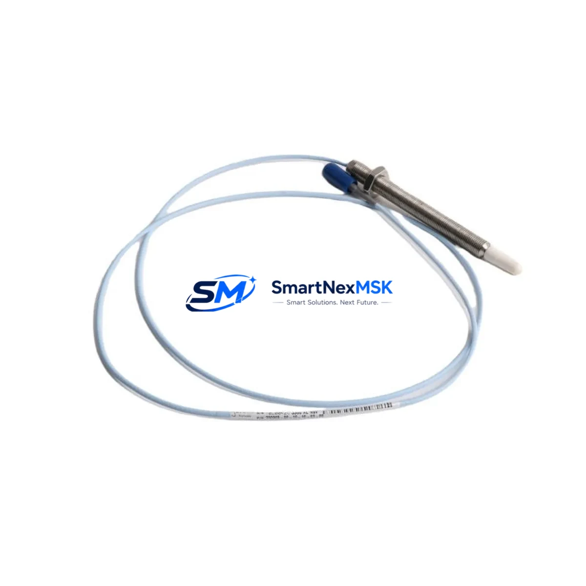
The Bently Nevada 330910-00-10-05-02-00 is a high-precision proximity transducer engineered for the 3300 XL Series vibration monitoring platform. As legacy 3300 Series installations approach end-of-support milestones, this module serves as the primary retrofit-ready replacement for facilities managing rotating machinery protection systems in power generation, oil & gas, petrochemical, and heavy industrial environments. Whether you are replacing a discontinued 330905 or 330930 transducer, upgrading a 3300/16 rack to a 3300 XL architecture, or restoring a failed channel in an existing Bently Nevada System 1 configuration, the 330910-00-10-05-02-00 provides a direct, field-verified upgrade path with minimal downtime exposure.
This transducer operates on the standard Bently Nevada proximitor/transducer signal chain, delivering a -18 VDC bias voltage output compatible with the 3300 XL Proximitor Sensor ecosystem. The 5-meter armored extension cable and 2-meter probe assembly dimensions are consistent with the original 330900 series footprint, allowing direct substitution in most existing conduit runs and junction box configurations without structural modification to the control cabinet or field wiring tray.
Upgrade Compatibility Table
| Parameter | 330910-00-10-05-02-00 | Legacy 330905 / 330930 |
|---|---|---|
| Probe Tip Diameter | 8 mm | 8 mm |
| Extension Cable Length | 5 m (standard) | 5 m |
| Bias Voltage Output | -18 VDC nominal | -18 VDC nominal |
| Signal Range | -2 to -18 VDC | -2 to -18 VDC |
| Target Material Compatibility | AISI 4140 steel | AISI 4140 steel |
| Connector Type | MIL-C-5015 (standard) | MIL-C-5015 |
| Rack Interface | 3300 XL Proximitor module | 3300/16 or 3300 XL |
| Communication Compatibility | System 1 / TDI Modbus | System 1 / TDI Modbus |
| Installation Requirement | Standard 3300 XL bracket | Existing bracket reusable |
| Retrofit Recommendation | Direct replacement | No mechanical rework needed |
| Commissioning Focus | Gap voltage, scale factor verification | Same procedure |
| Warranty | 12 Months | N/A (discontinued) |
Retrofit Planning for Existing Automation Systems
A successful retrofit of the 330910-00-10-05-02-00 into an operating plant begins well before the physical swap. Engineers should first audit the existing 3300 XL Proximitor module — typically a 330180 or 330185 Proximitor Sensor — to confirm the input channel is configured for the correct scale factor (200 mV/mil or 7.87 V/mm). If the rack houses a 3300/16 Monitor, verify that the backplane slot assignment and I/O termination block wiring match the new transducer’s pinout before powering down the channel.
In multi-channel vibration monitoring panels, the 330910-00-10-05-02-00 is commonly installed alongside the 3300/25 Dual Voting Logic module and the 3300/55 Keyphasor module, both of which must remain energized during a single-channel hot-swap to preserve system voting integrity. Where the plant uses a 3500 Series rack in parallel for redundancy, the 3500/42M Proximitor I/O module should be cross-checked for address mapping before the replacement transducer is commissioned.
For facilities migrating from older 7200 Series transducers to the 3300 XL platform, the 330910-00-10-05-02-00 requires a new proximitor — the 330180-51-05 is the recommended companion unit — and the field cable run should be inspected for impedance continuity. The 3300 XL system’s TDI (Transducer Driver Interface) communication link to System 1 software must be re-validated after any transducer substitution to ensure that alarm setpoints, danger thresholds, and trend data channels are correctly mapped to the new hardware address.
Power supply capacity in the control cabinet is a critical pre-check item. The 330910-00-10-05-02-00 draws from the rack’s -24 VDC bus via the Proximitor module. If the existing Bently Nevada PS-01 or equivalent rack power supply is already loaded near capacity due to additional I/O expansion cards or a recently added 3300/95 Communication Gateway module, a load calculation must be performed before adding the replacement transducer channel. Failure to verify power headroom is one of the most common causes of unexplained channel faults during post-retrofit commissioning.
HMI screen updates in the plant’s DCS or SCADA environment — whether running on a Rockwell FactoryTalk View, Wonderware InTouch, or Emerson DeltaV HMI platform — should be scheduled as part of the retrofit scope. Tag renaming, faceplate reconfiguration, and alarm acknowledgment logic tied to the old transducer address must be updated before the new 330910-00-10-05-02-00 channel is placed in service. Skipping this step frequently results in nuisance alarms or masked danger conditions during the first 24 hours of post-retrofit operation.
Downtime Control During System Migration
Minimizing unplanned downtime during a 330910-00-10-05-02-00 retrofit requires a structured pre-outage preparation protocol. Begin by downloading and archiving the current System 1 configuration database, including all channel scale factors, alarm setpoints, and historical trend baselines. This backup ensures that if the replacement transducer requires gap voltage re-adjustment beyond the standard -10.0 VDC ± 0.5 VDC acceptance window, the original configuration can be restored without re-engineering the monitoring logic from scratch.
Where plant operations permit, a single-channel bypass using the 3300 XL’s built-in channel inhibit function allows the faulty or discontinued transducer to be isolated while the remaining channels in the voting group continue to protect the machine. This approach is particularly effective in 2-out-of-3 voting configurations where removing one channel does not reduce the system below its minimum protective voting threshold. Coordinate with the control room operator to confirm that the bypass is logged in the plant’s Management of Change (MOC) system before proceeding.
Physical installation of the 330910-00-10-05-02-00 should follow the Bently Nevada Installation Manual (document 141078-01), paying particular attention to the probe-to-target gap setting procedure. Use a calibrated digital voltmeter to measure the static gap voltage at the Proximitor output terminal before reconnecting the monitor input. A gap voltage outside the -9.5 to -10.5 VDC range at the nominal 50-mil (1.27 mm) installation gap indicates either a probe positioning error or a target material mismatch that must be resolved before the channel is returned to service.
Once the transducer is installed and gap-verified, perform a full channel functional test by introducing a known vibration signal via a calibrated shaker or by observing the machine’s normal startup transient. Confirm that the System 1 trend display shows a clean, noise-free signal and that the 3300 XL monitor’s OK relay is energized before removing the channel inhibit. Document the as-left gap voltage, scale factor, and alarm setpoints in the plant’s instrument calibration record to support future maintenance cycles and regulatory compliance audits.
Retrofit Support FAQ
Q1: Is the 330910-00-10-05-02-00 a direct drop-in replacement for the discontinued 330905-00-10-05-02-00?
Yes. The 330910-00-10-05-02-00 is the current production successor to the 330905 series. Probe tip diameter, extension cable length, connector type, and bias voltage output are identical. No mechanical rework or wiring modification is required for a direct substitution in an existing 3300 XL installation.
Q2: What commissioning steps are mandatory after installing the replacement transducer?
At minimum: (1) verify static gap voltage at the Proximitor output terminal (-9.5 to -10.5 VDC at nominal gap), (2) confirm scale factor setting in the 3300 XL monitor matches the transducer’s rated sensitivity (200 mV/mil), (3) validate System 1 channel mapping and alarm setpoints, and (4) perform a functional vibration response test before returning the channel to protective service.
Q3: Does the 330910-00-10-05-02-00 work with both the 3300/16 and 3300 XL monitor racks?
Yes, with qualification. The transducer is fully compatible with 3300 XL Proximitor modules. For legacy 3300/16 racks, compatibility depends on the installed Proximitor version — confirm the Proximitor part number before ordering. In mixed-rack environments, the 3300 XL Proximitor is the recommended interface for this transducer.
Q4: What warranty coverage is provided, and what does it include?
All units ship with a 12-month warranty covering manufacturing defects, electrical performance out-of-specification conditions, and connector integrity failures. Each unit undergoes pre-shipment functional testing including bias voltage output verification and insulation resistance check. Warranty claims are processed within 5 business days of receipt of the returned unit with a completed failure report.
© 2026 SMARTNEXMSK. All rights reserved.
Original Source: https://smartnexmsk.com
Contact: sales@smartnexmsk.com | +86 18259474341


