Bently Nevada 330910-00-11-05-01-00 3300 XL Retrofit-Ready Proximity Transducer: Compatible Modernization for Legacy Vibration Monitoring Systems
The Bently Nevada 330910-00-11-05-01-00 is a high-precision eddy-current proximity transducer engineered for the 3300 XL Series vibration monitoring platform. As original equipment reaches end-of-life or becomes increasingly difficult to source through OEM channels, this retrofit-ready replacement provides a verified drop-in solution for rotating machinery protection systems in power generation, petrochemical, oil and gas, and heavy industrial environments. Whether you are managing a planned upgrade, responding to an unplanned failure, or executing a phased modernization of your control infrastructure, this transducer is stocked, tested, and ready to ship.
The 330910-00-11-05-01-00 operates within the standard 3300 XL transducer system architecture, which pairs the proximity probe with a compatible extension cable and a 3300 XL proximitor/seismic monitor. When replacing a failed or discontinued unit, engineers must verify that the replacement transducer matches the original gap voltage range, sensitivity factor (typically 7.87 V/mm or 200 mV/mil), and cable length to maintain calibrated system performance. The 3300 XL Series proximitor accepts inputs from the transducer system and converts the raw eddy-current signal into a conditioned output for the vibration monitor rack — typically housed in a 3500 Series monitoring system or an equivalent legacy rack.
Upgrade Compatibility Table
| Parameter | Detail |
|---|---|
| SKU / Part Number | 330910-00-11-05-01-00 |
| Series Compatibility | Bently Nevada 3300 XL Series |
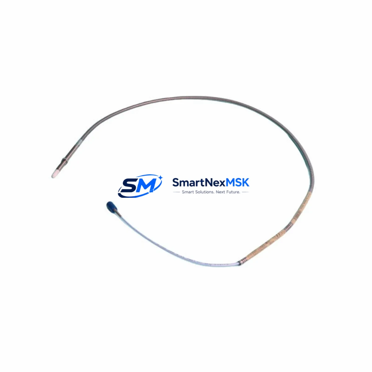
| Transducer Type | Eddy-Current Proximity Transducer |
| Sensitivity | 7.87 V/mm (200 mV/mil) nominal |
| Probe Tip Diameter | 11 mm |
| Cable Length | 5 m (integral cable) |
| Connector Type | Standard 3300 XL coaxial connector |
| Installation Requirement | Threaded mounting, verify bracket and target gap (typically 1.0–2.0 mm) |
| Communication / Signal | Analog voltage output; compatible with 3300 XL proximitor and 3500 monitor rack |
| Replacement Recommendation | Direct drop-in for 330910-00-11-05-01-00; verify extension cable part number separately |
| Commissioning Notes | Re-gap probe after installation; verify OK voltage and gap voltage at proximitor output |
| Warranty | 12-Month Warranty included |
Retrofit Planning for Existing Automation Systems
Replacing the 330910-00-11-05-01-00 in an operating plant requires a structured approach that accounts for the full transducer system — not just the probe itself. The complete measurement chain begins at the probe tip and runs through the extension cable (such as the 330130-045-00-00 or equivalent 3300 XL extension cable) to the proximitor module mounted in the field junction box or directly on the monitor rack. The proximitor — for example, a 3300 XL 8mm proximitor or a 3300 XL 11mm proximitor depending on your installed configuration — conditions the raw eddy-current signal before it reaches the 3500/40M or 3500/42M vibration monitor card in the 3500 Series rack.
During retrofit planning, engineers should pull the existing loop drawing and confirm the following: the probe mounting thread size and bracket clearance, the extension cable routing and connector condition, the proximitor supply voltage (typically -24 VDC from the 3500 rack power supply), and the OK relay setpoints configured in the 3500 rack software. If the 3500 rack is also being upgraded or replaced, the 3500/01 rack power supply and 3500/20 rack interface module should be inspected for compatibility with the new transducer system configuration.
For plants running older 3300 Series (non-XL) monitors, a direct swap to the 3300 XL transducer system may require a proximitor upgrade as well. In these cases, the 3300/16-02-01-00 proximitor or its XL equivalent should be evaluated alongside the probe replacement. Similarly, if the control system communicates vibration data to a DCS or safety system via a 3500 rack Modbus or 4–20 mA output, the signal scaling and alarm setpoints must be re-verified after the transducer swap to ensure the downstream PLC or DCS — such as a GE Mark VI turbine control system or a Honeywell Experion PKS — receives correctly calibrated data.
Where the plant uses a System 1 Evolution software platform for online machinery diagnostics, the transducer replacement should be logged in the asset database and the gap voltage trend reset to establish a new baseline. This is particularly important for machines with tight vibration alarm margins, such as high-speed compressors or steam turbines, where a miscalibrated transducer can trigger nuisance trips or — worse — mask developing faults.
Downtime Control During System Migration
Minimizing unplanned downtime during a transducer replacement is a primary concern for any rotating equipment engineer. The 330910-00-11-05-01-00 is designed for straightforward field replacement, but the process must be executed with care to protect the original program logic, alarm configurations, and HMI display mappings in the connected monitoring system.
Before removing the failed transducer, document the existing gap voltage reading at the proximitor output terminal — this is your baseline for re-commissioning. If the machine cannot be taken offline immediately, the 3500 rack can often be placed in bypass mode for the affected channel, allowing the machine to continue operating under reduced monitoring while the replacement is prepared. Once the new 330910-00-11-05-01-00 is installed and the probe gap is set to the target voltage (typically -10.0 VDC ±0.5 VDC for a 1.0 mm gap on a steel target), the channel can be brought back online and the bypass removed.
All alarm setpoints — including the danger and alert levels for radial vibration, axial position, or differential expansion depending on the measurement application — should be confirmed against the original engineering specification before returning the machine to service. If the 3500 rack communicates with a turbine control system or safety instrumented system (SIS), the I/O signal integrity should be verified at the receiving end before the bypass is cleared. This end-to-end verification loop, from probe gap to DCS display, is the most reliable way to confirm that the replacement has been completed correctly and that control continuity is maintained throughout the migration.
Retrofit Support FAQ
Q1: Is the 330910-00-11-05-01-00 a direct replacement for the original Bently Nevada part?
Yes. This unit is a verified retrofit-compatible replacement for the original 330910-00-11-05-01-00 proximity transducer. It matches the original sensitivity, connector type, probe tip diameter, and cable length. No mechanical or electrical modifications are required for a standard drop-in installation in a 3300 XL transducer system.
Q2: What commissioning steps are required after installation?
After mechanical installation, set the probe gap to achieve the target OK voltage at the proximitor output (typically -10.0 VDC ±0.5 VDC). Verify the OK relay status on the 3500 monitor rack, confirm alarm setpoints are unchanged, and check the signal at the DCS or control system input. Document the new gap voltage as the baseline for future trend monitoring.
Q3: Does this transducer require a matching extension cable or proximitor?
The 330910-00-11-05-01-00 is an integral-cable transducer with a 5 m cable. If your installation requires a longer cable run, a compatible 3300 XL extension cable must be used — do not substitute with non-3300 XL cables, as impedance mismatches will affect calibration. The proximitor must also be a 3300 XL 11mm type to match the probe tip diameter and sensitivity specification.
Q4: What warranty and pre-shipment testing is included?
Every unit ships with a 12-month warranty covering manufacturing defects and performance conformance. Pre-shipment testing includes gap voltage verification, sensitivity check, and connector integrity inspection. A test report is available upon request. Units are packaged to IEC transport standards to prevent damage during international shipping.
© 2026 SMARTNEXMSK. All rights reserved.
Original Source: https://smartnexmsk.com
Contact: sales@smartnexmsk.com | +86 18259474341


