Bently Nevada 330910-00-11-10-01-00 Retrofit-Ready Proximity Transducer for 3300 XL Control Systems
The Bently Nevada 330910-00-11-10-01-00 is a high-precision proximity transducer engineered for seamless integration into 3300 XL NSv vibration monitoring and machinery protection systems. As legacy Bently Nevada installations approach end-of-life or face discontinued spare part availability, this unit serves as the definitive retrofit-ready replacement — preserving signal integrity, rack compatibility, and measurement accuracy without requiring reprogramming of existing monitor logic or HMI display configurations.
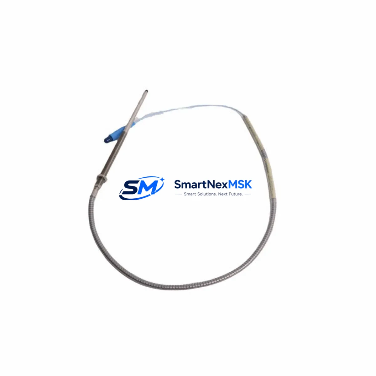
Designed for industrial environments where uptime is non-negotiable, the 330910-00-11-10-01-00 supports direct substitution in rotating machinery protection applications including turbines, compressors, pumps, and gearboxes. Its eddy-current sensing principle delivers reliable non-contact displacement measurement, making it the preferred choice for engineers managing aging control infrastructure across petrochemical, power generation, and heavy manufacturing facilities.
Upgrade Compatibility Table
| Parameter | Detail |
|---|---|
| SKU / Part Number | 330910-00-11-10-01-00 |
| Brand | Bently Nevada |
| Series | 3300 XL NSv Proximity Transducer System |
| Sensing Principle | Eddy-Current (Non-Contact) |
| Cable Length | 1 m (extension cable compatible) |
| Thread Size | M10 x 1 (standard 3300 XL mount) |
| Connector Type | 3-pin MIL-C-5015 compatible |
| Compatible Monitors | 3300/16, 3300/20, 3300/25, 3300 XL series |
| Rack / Backplane Interface | 3300 XL rack — direct slot replacement |
| Communication Protocol | Analog 4–20 mA / voltage output; compatible with Modbus RTU via 3500 gateway |
| Replacement Recommendation | Direct drop-in for discontinued 330910 variants; verify gap voltage at commissioning |
| Commissioning Focus | Gap voltage calibration, polarity check, signal chain verification to monitor card |
| Installation Requirement | Grounded target surface; non-conductive mounting sleeve if required |
| Warranty | 12 Months — covers manufacturing defects and signal performance |
Retrofit Planning for Existing Automation Systems
When integrating the 330910-00-11-10-01-00 into an existing machinery protection architecture, a structured retrofit plan is essential to avoid signal chain disruptions. Begin by auditing the current rack configuration — most 3300 XL installations use a 3300/16 or 3300/20 monitor card paired with a dedicated power supply module such as the Bently Nevada 3300/05 Power Supply. Confirm that the rack’s backplane bus voltage (typically –24 VDC) is within specification before inserting the replacement transducer system.
Terminal wiring should be mapped against the original loop drawing. The 330910-00-11-10-01-00 uses a standard three-conductor shielded cable arrangement: power, signal, and common. If the existing installation uses a Bently Nevada 330130 extension cable or 330180 armored extension cable, verify that the total system cable length does not exceed the driver’s calibrated range — typically 5 m or 9 m depending on the 330180 proximitor/driver in use.
For sites migrating from older 3300/25 dual-channel monitors to the current 3300 XL platform, module address configuration must be re-verified in the System 1 Evolution or Bently Nevada 3500 Rack software environment. The 3500 series rack, which is the natural upgrade path from legacy 3300 installations, supports the same transducer signal standard, allowing the 330910-00-11-10-01-00 to interface with 3500/42M Proximitor I/O Module cards without signal conditioning changes.
HMI screen updates are typically minimal when performing a like-for-like transducer swap. However, if the site is simultaneously upgrading from a legacy Bently Nevada 1900/65A general-purpose monitor to a 3300 XL or 3500 platform, operators should plan for HMI tag remapping and alarm setpoint re-entry. Coordinate with the DCS or SCADA integrator to ensure that vibration trend data continuity is maintained across the cutover window.
I/O expansion considerations are relevant when the retrofit coincides with a broader control system upgrade. Sites adding new measurement points — for example, extending axial position monitoring to a second compressor train — may require additional 3300 XL rack slots or a supplementary 3500/22M Transient Data Interface module. Plan rack space allocation before procurement to avoid field delays.
Downtime Control During System Migration
Minimizing production downtime during a proximity transducer replacement requires a disciplined pre-outage preparation protocol. Before the maintenance window opens, pre-configure the replacement 330910-00-11-10-01-00 on a bench test fixture using a Bently Nevada 330100 proximitor and a calibrated target disk. Verify gap voltage output (typically –10.0 VDC at 2.0 mm gap for standard 3300 XL calibration) and document the reading for field comparison.
During the outage, follow a structured swap sequence: isolate the monitor channel, remove the existing transducer, install the 330910-00-11-10-01-00, reconnect the extension cable, and restore power to the monitor card. Use a Bently Nevada TK-3 calibration tool or equivalent gap-setting fixture to confirm the installed gap before returning the channel to service. This approach typically reduces field commissioning time to under 30 minutes per measurement point.
To protect existing program logic, export a full configuration backup from the System 1 Evolution software or the 3500 rack’s configuration utility before any hardware change. This backup preserves alarm setpoints, danger limits, time-delay settings, and channel assignments — ensuring that the control system can be restored to its pre-outage state within minutes if an unexpected issue arises during commissioning.
For multi-point retrofits across a large turbine or compressor train, consider a phased replacement strategy: replace one measurement plane at a time, verify signal integrity, and return that channel to automatic protection before proceeding to the next. This approach maintains partial machinery protection throughout the outage and reduces the risk of a full protection system bypass.
Retrofit Support FAQ
Q1: Is the 330910-00-11-10-01-00 a direct replacement for other 330910 suffix variants?
The 330910 series uses a suffix structure that encodes cable length, connector type, and temperature rating. The -00-11-10-01-00 configuration specifies a 1 m cable, standard temperature rating, and MIL-spec connector. Before substituting a different suffix variant, confirm that cable length and connector pinout match your existing installation. In most 3300 XL retrofit scenarios, this variant is interchangeable with adjacent suffix configurations provided the total system cable length remains within the proximitor’s calibrated range.
Q2: What wiring checks are required before powering up the replacement transducer?
Verify shield continuity, confirm that the common conductor is grounded at one end only (typically at the monitor card), and check for cable insulation resistance to ground (minimum 1 MΩ). Inspect the extension cable connector for corrosion or pin damage before mating. After power-up, measure gap voltage at the monitor card’s test point and compare against the bench-calibrated reference value documented during pre-outage preparation.
Q3: Will this transducer work with a 3500 series rack without recalibration?
Yes. The 330910-00-11-10-01-00 is compatible with the 3500 series rack when paired with the appropriate 3500/42M Proximitor I/O Module. The 3500 rack’s configuration software allows channel-level calibration adjustment, so minor gap voltage offsets can be corrected in software without mechanical repositioning of the transducer. Full system calibration verification is still recommended after any hardware change.
Q4: What does the 12-month warranty cover?
The 12-month warranty covers manufacturing defects, signal output accuracy within published specifications, and connector integrity under normal operating conditions. Each unit undergoes pre-shipment functional testing including gap voltage output verification, insulation resistance check, and connector continuity test. Warranty claims are supported by our technical team at sales@smartnexmsk.com. Units showing field damage due to incorrect installation, over-range mechanical contact, or electrical overstress are evaluated on a case-by-case basis.
© 2026 SMARTNEXMSK. All rights reserved.
Original Source: https://smartnexmsk.com
Contact: sales@smartnexmsk.com | +86 18259474341


