Bently Nevada 330910-00-13-05-01-00 3300 XL Retrofit Proximity Transducer: Compatible Modernization for Legacy Vibration Monitoring Systems
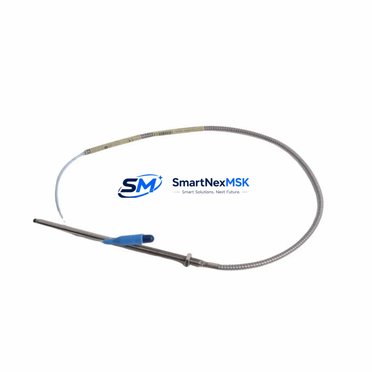
The Bently Nevada 330910-00-13-05-01-00 is a precision eddy-current proximity transducer engineered for the 3300 XL Series vibration monitoring platform. As legacy rotating machinery protection systems approach end-of-life or face discontinued spare parts availability, this unit serves as a direct retrofit-ready replacement that preserves existing wiring infrastructure, rack architecture, and signal conditioning logic without requiring a full system overhaul.
Industrial facilities operating gas turbines, steam turbines, compressors, and pumps that rely on the Bently Nevada 3300 XL platform frequently encounter challenges sourcing original transducer assemblies. The 330910-00-13-05-01-00 addresses this gap by offering verified compatibility with the 3300 XL proximitor/seismic monitor rack, maintaining the standard -24 VDC bias voltage output and 200 mV/mil (7.87 V/mm) scale factor that downstream signal processors and System 1 condition monitoring software expect.
For retrofit engineers and reliability teams, this transducer integrates directly into existing Bently Nevada 3300 XL Extension Cable assemblies and Proximitor sensor housings without modification to terminal block wiring or cable routing. The standard TNC connector interface and 5-meter or 9-meter cable configurations align with the original installation footprint, minimizing downtime during scheduled turnaround windows.
Upgrade Compatibility Table
| Parameter | 330910-00-13-05-01-00 (This Unit) | Legacy / Replaced Models | Retrofit Notes |
|---|---|---|---|
| Platform Compatibility | Bently Nevada 3300 XL Series | 3300 Series (earlier revision) | Verify rack slot type: 3300/16 or 3300/20 monitor card |
| Output Scale Factor | 200 mV/mil (7.87 V/mm) | 200 mV/mil | No recalibration required if scale factor matches |
| Bias Voltage | -24 VDC nominal | -24 VDC | Confirm Proximitor supply voltage at terminal strip |
| Connector Interface | TNC (standard) | TNC | Direct plug-in; no adapter required |
| Cable Length | 5 m / 9 m options | 5 m / 9 m | Match existing extension cable length for gap calibration |
| Installation Type | Threaded body, radial/axial mount | Threaded body | Confirm thread size (8 mm standard) and probe tip clearance |
| Communication Protocol | Analog 4–20 mA / voltage output | Analog | Compatible with System 1 software and DCS analog input cards |
| Replacement Recommendation | Direct drop-in for 3300 XL rack | Discontinue 3300 (non-XL) if possible | Upgrade Proximitor to 3300 XL/16 if using older monitor card |
| Commissioning Focus | Gap voltage, alert/danger setpoints | Same | Re-verify gap voltage (-10 to -18 VDC typical) after installation |
| Warranty | 12-Month Warranty — covers manufacturing defects and functional performance under specified operating conditions | ||
Retrofit Planning for Existing Automation Systems
Successful integration of the 330910-00-13-05-01-00 into an operating plant begins with a thorough pre-outage audit. Reliability engineers should document the existing Proximitor sensor model — typically a Bently Nevada 3300 XL 8 mm Proximitor — and confirm that the installed extension cable, such as a 330130-045-00-00 or 330130-080-00-00 series, is within its rated service life. Damaged or aged extension cables are a common source of signal noise that can be misattributed to the transducer itself.
At the rack level, verify the monitor card type. The 3300/16-02-01-01-00 and 3300/20-01-01-00 monitor cards each have specific channel configuration requirements accessible through the Rack Configuration Software (RCS). If the plant DCS — whether a Honeywell Experion PKS, Emerson DeltaV, or ABB 800xA system — receives vibration data via a 4–20 mA analog input card, confirm that the input range and engineering unit scaling in the DCS controller logic match the transducer’s output scale factor before energizing the replacement unit.
Terminal block wiring at the junction box should be inspected for corrosion, loose ferrules, and correct polarity. The standard three-wire configuration (power, common, output) must be preserved. If the facility uses a Bently Nevada 3500 Series rack in parallel for overspeed or thrust monitoring, ensure that the signal routing between the 3300 XL rack and the 3500/42M Proximitor I/O Module is not disrupted during the transducer swap.
For plants migrating from older Bently Nevada 7200 Series transducers to the 3300 XL platform, a gap recalibration procedure is mandatory. The 7200 Series uses a different scale factor (100 mV/mil), and any HMI display configured in a GE iFIX, Wonderware InTouch, or Ignition SCADA system must have its engineering unit conversion updated accordingly. Failure to update the HMI scaling will result in false alert or danger conditions immediately after commissioning.
Where I/O expansion is required — for example, adding radial vibration monitoring to a previously unmonitored bearing — the 3300 XL rack can accommodate additional monitor cards alongside the existing 3300/16 cards. This avoids the need to install a separate rack enclosure and preserves the existing communication link to the plant historian or condition monitoring server running Bently Nevada System 1 software.
Downtime Control During System Migration
Minimizing unplanned downtime is the primary operational constraint in any transducer retrofit. The 330910-00-13-05-01-00 is pre-tested and shipped with a functional verification report, allowing maintenance teams to confirm output characteristics on the bench before the scheduled outage window opens.
The recommended migration sequence is: (1) bench-test the replacement transducer against a reference target at the specified gap distance to confirm scale factor and bias voltage; (2) during the outage, disconnect the existing transducer at the junction box terminal strip without disturbing the extension cable; (3) install the new transducer, reconnect terminals, and restore power to the Proximitor; (4) measure gap voltage at the monitor card terminal and adjust probe position until the gap voltage falls within the -10 to -18 VDC window specified in the 3300 XL installation manual; (5) verify alert and danger setpoints in the RCS software and confirm that the DCS and SCADA displays reflect live vibration data within expected baseline ranges before releasing the machine to operations.
For critical machinery where a hot-swap is required, the 3300 XL rack supports channel bypass mode, which allows a single channel to be taken out of service without triggering a system trip. This feature is essential for maintaining control continuity on operating turbines or compressors where a full shutdown is not permissible. Coordinate with the control room operator to activate bypass mode before disconnecting the old transducer, and deactivate bypass only after the new unit has been verified in service.
All original program logic in the DCS controller — including vibration trend calculations, alarm management sequences, and historian tag assignments — remains intact during a like-for-like transducer replacement. No PLC or DCS program download is required, which further reduces the risk of introducing logic errors during the migration window.
Retrofit Support FAQ
Q1: Is the 330910-00-13-05-01-00 a direct replacement for earlier 3300 Series (non-XL) transducers?
In most cases, yes — provided the installed Proximitor is a 3300 XL model and the extension cable length matches. If the existing Proximitor is a pre-XL 3300 Series unit, it should be upgraded to a 3300 XL 8 mm Proximitor at the same time to ensure full system compatibility and to maintain the manufacturer’s recommended signal chain integrity.
Q2: What commissioning checks are required after installation?
After physical installation, measure the gap voltage at the monitor card terminal strip. The acceptable range is -10 to -18 VDC for an 8 mm probe at the nominal gap distance (typically 1.0–1.5 mm). Confirm alert and danger setpoints in the RCS software, verify that the DCS analog input is reading within the expected engineering unit range, and check that the System 1 condition monitoring software is logging data from the new channel before returning the machine to service.
Q3: Can this transducer be used with Modbus or PROFIBUS-based DCS systems?
The 330910-00-13-05-01-00 outputs an analog voltage signal processed by the 3300 XL monitor card, which then communicates with the DCS via a 4–20 mA analog output or, in some rack configurations, via a Bently Nevada 3500/92 Communication Gateway that supports Modbus RTU or TCP/IP. The transducer itself is protocol-agnostic; protocol compatibility is determined at the rack and gateway level.
Q4: What does the 12-month warranty cover, and how is it processed?
The 12-month warranty covers manufacturing defects and verified functional failures under normal operating conditions as specified in the Bently Nevada 3300 XL installation documentation. Units that fail within the warranty period should be returned with a completed failure description form. Replacement units are dispatched after inspection confirmation. Warranty does not cover damage resulting from incorrect installation, gap voltage outside the specified range, or use with incompatible Proximitor models.
© 2026 SMARTNEXMSK. All rights reserved.
Original Source: https://smartnexmsk.com
Contact: sales@smartnexmsk.com | +86 18259474341


