Bently Nevada 330910-00-13-10-01-00 Spare for 3300 XL Automation: Precision Spare Parts for Industrial Downtime Control
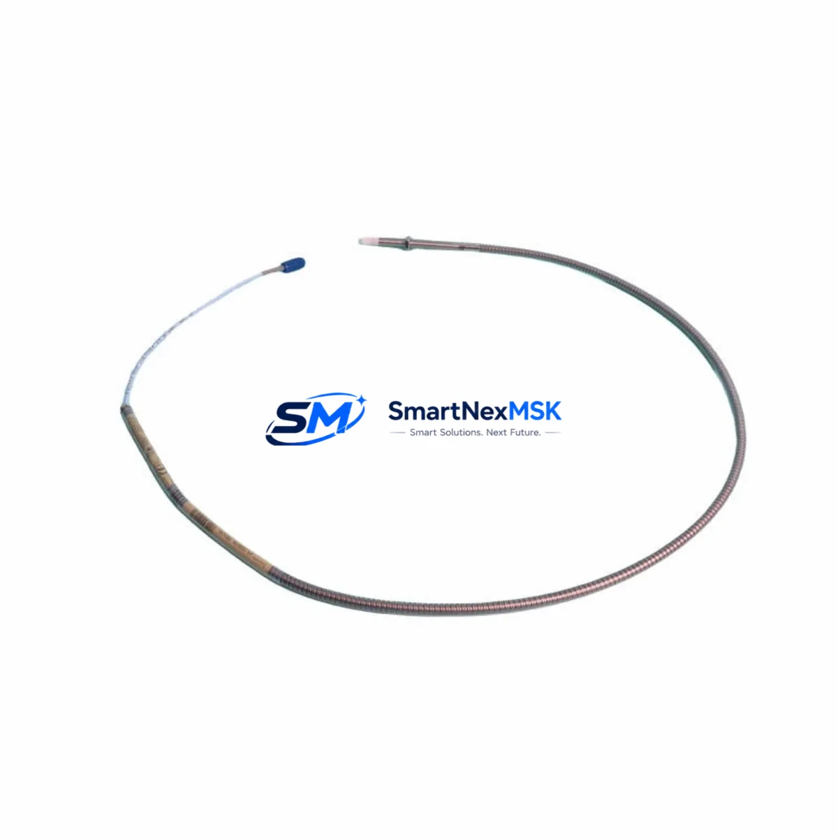
The Bently Nevada 330910-00-13-10-01-00 is an original 8mm eddy-current proximity transducer engineered for the 3300 XL Series continuous machinery monitoring system. Designed for radial vibration, axial position, and differential expansion measurement on rotating equipment, this transducer is a critical spare for turbines, compressors, pumps, and gearboxes operating in oil & gas, power generation, petrochemical, and heavy industrial environments. Maintaining a verified stock of this component directly reduces unplanned downtime risk and supports rapid fault isolation during machinery health events.
Each unit shipped by SMARTNEXMSK is sourced from authorized supply channels, individually inspected, and function-tested prior to dispatch. A 12-month warranty is included with every order, covering manufacturing defects and performance deviations from OEM specifications. Our global logistics network supports urgent spare parts requirements with expedited shipping options to minimize machinery downtime.
Spare Maintenance Table
| Part Number / SKU | 330910-00-13-10-01-00 |
| Brand | Bently Nevada |
| Series | 3300 XL |
| Product Type | Eddy-Current Proximity Transducer |
| Probe Diameter | 8 mm |
| Measurement Function | Radial Vibration, Axial Position, Differential Expansion |
| Cable Length | 1.0 m (standard; extension cable required for full system) |
| Output Signal | –24 VDC bias; sensitivity 7.87 V/mm (200 mV/mil) |
| Operating Temperature | –35°C to +177°C (probe tip) |
| Target Material Compatibility | AISI 4140 steel (standard); verify for non-standard alloys |
| Connector Type | Integral coaxial connector, 3300 XL system compatible |
| System Compatibility | Bently Nevada 3300 XL Monitor Series (3300/16, 3300/20, 3300/25, 3300/46, 3300/55) |
| Installation Environment | Hazardous area rated; suitable for Zone 1/2, Class I Div 1/2 |
| Mounting | Threaded probe tip; bracket or direct-mount per OEM specification |
| Origin | USA |
| Condition | Original, New / Surplus New |
| Pre-shipment Testing | Function-tested; gap voltage and sensitivity verified |
| Warranty | 12 Months — Manufacturing Defects & Performance |
| Lead Time | In-stock: ships within 1–3 business days |
Maintenance Planning for Continuous Operation
When replacing the 330910-00-13-10-01-00 proximity transducer during a planned or emergency maintenance event, a disciplined maintenance engineer will treat this as an opportunity to audit the entire vibration monitoring loop and adjacent control cabinet components. The transducer does not operate in isolation — its performance depends on the integrity of the full signal chain from probe tip to monitor rack output.
Begin by inspecting the 330130-080-00-05 extension cable that connects the probe to the proximitor. Cable jacket damage, connector corrosion, or kinking near the probe bracket are common failure contributors that are frequently overlooked when only the transducer is replaced. Pair this with a check of the 330180-X0-05 proximitor/driver (the signal conditioning module), verifying its output bias voltage falls within the –18 VDC to –26 VDC window under no-load conditions.
At the monitor rack level, confirm the 3300/16 or 3300/20 vibration monitor card is seated correctly and that its OK relay output is functioning. If the system uses a 3300/46 Keyphasor module, verify the once-per-revolution reference signal is clean and free of noise — a degraded Keyphasor signal can produce false vibration alarms that mask real machinery faults. For axial position monitoring loops, the 3300/55 Dual Voting Trip module should be tested for correct setpoint response after any transducer replacement.
Within the control cabinet, inspect the 24 VDC power supply module feeding the proximitor rail. Voltage ripple or sag under load can introduce measurement noise that mimics real vibration. Terminal blocks on the signal wiring — particularly Phoenix Contact or Weidmuller DIN-rail terminal strips — should be torque-checked and inspected for oxidation. Loose or corroded terminals are a leading cause of intermittent OK-relay trips in eddy-current monitoring systems.
If the machine is part of a Safety Instrumented System (SIS), coordinate with the safety engineer to verify that replacing the transducer does not require a partial stroke test or proof test of the associated solenoid valve or trip relay in the protective loop. For older 3300 Series installations being extended beyond their original design life, consider stocking the 330905-00-08-10-01-00 (5mm variant) and 330930-00-13-10-01-00 (reverse-mount variant) as cross-reference spares to cover adjacent measurement points on the same machine train.
Site Replacement Workflow
Step 1 — Pre-replacement verification: Confirm the replacement unit SKU 330910-00-13-10-01-00 matches the installed probe diameter (8mm), cable length, and connector type. Cross-reference against the machine’s vibration monitoring loop drawing and the 3300 XL system configuration record.
Step 2 — Safe isolation: Follow site LOTO (Lockout/Tagout) procedures. Notify the control room to bypass the vibration monitor channel to prevent spurious trips during replacement. Do not remove the probe while the machine is running unless the monitor channel is confirmed bypassed.
Step 3 — Probe removal and gap measurement: Remove the old transducer and inspect the probe tip and target area for wear, scoring, or contamination. Clean the target surface before installing the replacement. Set the probe gap to the OEM-specified value (typically 1.0–1.5 mm for 8mm probes) using a non-ferrous feeler gauge or gap voltage measurement (–10.0 VDC ± 0.5 VDC at nominal gap).
Step 4 — Signal verification: After installation, verify the OK relay status at the monitor rack, confirm bias voltage at the proximitor output, and check that the vibration reading is within expected baseline range before removing the channel bypass.
Step 5 — Documentation: Record the replacement in the equipment maintenance log, including the new unit serial number, installation date, gap voltage reading, and technician sign-off. Update the spare parts inventory to trigger reorder of the consumed unit.
Spare Parts Support FAQ
Q1: Is the 330910-00-13-10-01-00 compatible with all 3300 XL monitor cards?
Yes. This 8mm proximity transducer is designed for use across the 3300 XL monitor family, including the 3300/16, 3300/20, 3300/25, 3300/46, and 3300/55 modules. Always verify the system configuration drawing to confirm the correct probe diameter and cable length for your specific measurement point before installation.
Q2: What pre-shipment testing is performed on each unit?
Every 330910-00-13-10-01-00 unit shipped by SMARTNEXMSK undergoes gap voltage verification, sensitivity check (7.87 V/mm ± 5%), and connector integrity inspection. Units that do not meet OEM performance specifications are quarantined and not dispatched. A test report is available upon request for critical applications.
Q3: Can this transducer replace older 3300 Series (non-XL) probes?
The 3300 XL series uses the same eddy-current operating principle as the earlier 3300 Series, but connector and cable specifications may differ. Confirm the proximitor model installed in your system before substituting. If your system uses a 330100-series proximitor, consult the compatibility matrix or contact our technical team for cross-reference confirmation.
Q4: What does the 12-month warranty cover?
The 12-month warranty covers manufacturing defects, connector failures, and performance deviations from OEM specifications under normal operating conditions. It does not cover damage resulting from incorrect installation, overvoltage, mechanical impact, or use outside the rated environmental envelope. Warranty claims are processed with return authorization; replacement units are dispatched within 5 business days of claim approval.
© 2026 SMARTNEXMSK. All rights reserved.
Original Source: https://smartnexmsk.com
Contact: sales@smartnexmsk.com | +86 18259474341


