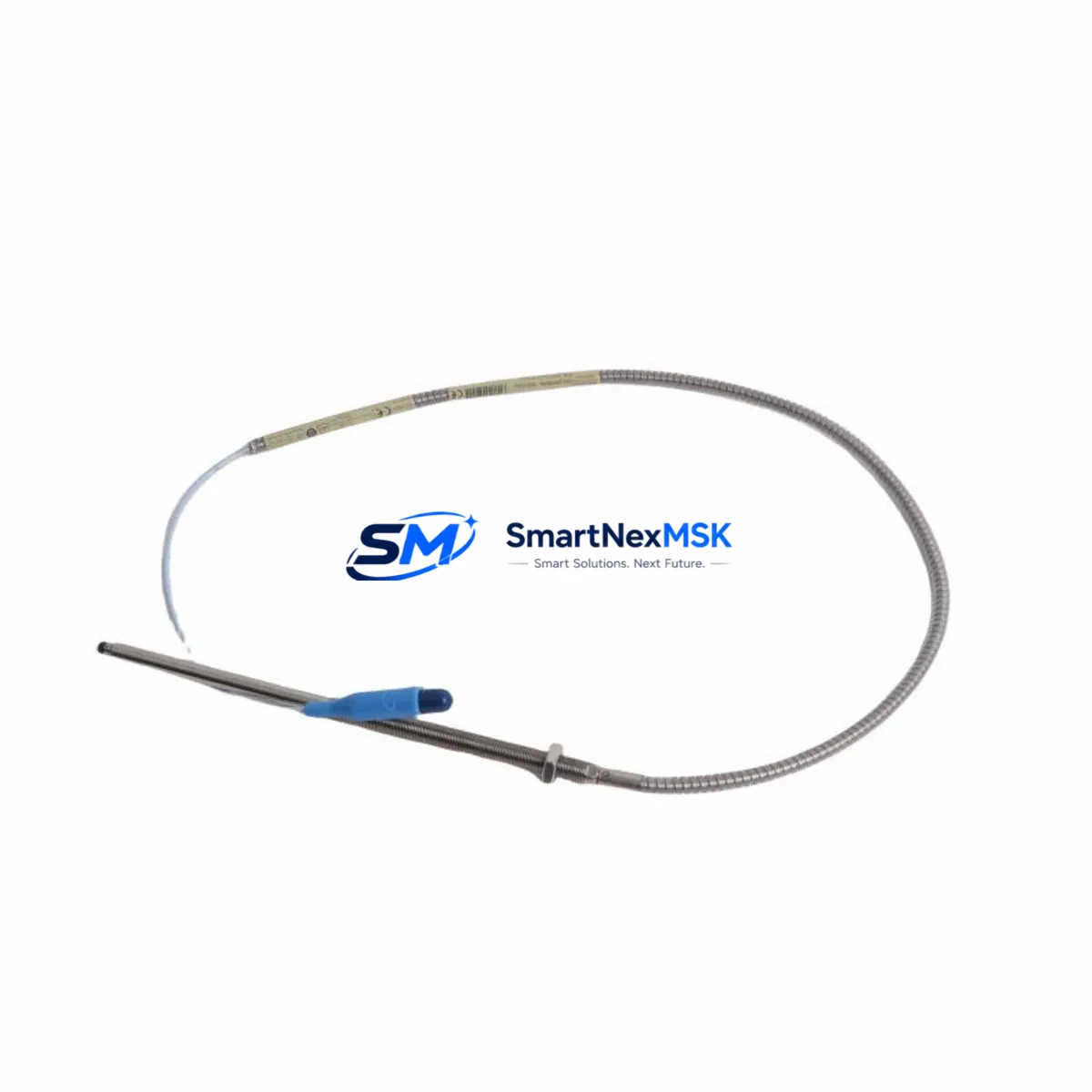
Bently Nevada 330910-00-14-05-02-00 Maintenance-Ready Spare 3300 XL Automation
The Bently Nevada 330910-00-14-05-02-00 is an original proximity transducer engineered for the 3300 XL Proximity Transducer System — one of the most widely deployed vibration monitoring platforms in rotating machinery protection across oil & gas, power generation, petrochemical, and heavy industrial facilities. When this transducer fails or degrades, the consequences extend beyond a single sensor: the entire vibration channel goes offline, leaving critical rotating assets — compressors, turbines, pumps, and gearboxes — unprotected and potentially subject to unplanned shutdown.
Sourced as an original spare, the 330910-00-14-05-02-00 is fully compatible with the Bently Nevada 3300 XL monitor system architecture. It integrates directly with the 3300 XL proximitor/seismic interface module and the associated signal conditioning chain without requiring recalibration of the monitoring rack. Maintenance engineers can execute a like-for-like replacement with confidence, restoring full vibration channel integrity and returning the machine to protected operation in the shortest possible time.
Spare Maintenance Table
| Parameter | Specification |
|---|---|
| Part Number | 330910-00-14-05-02-00 |
| Brand | Bently Nevada |
| Series | 3300 XL Proximity Transducer System |
| Product Type | Proximity Transducer (Eddy-Current) |
| Measurement Target | Shaft radial vibration, axial position, differential expansion |
| Cable Length | 5 m (extension cable configurable) |
| Tip Diameter | 5 mm |
| Thread Size | M10 × 1 |
| Operating Temperature | −35°C to +177°C (probe tip) |
| Supply Voltage | −24 VDC (via proximitor) |
| Output Signal | −2 VDC to −18 VDC linear range |
| Sensitivity | 7.87 V/mm (200 mV/mil) |
| Compatible Monitor | Bently Nevada 3300 XL Series |
| Compatible Proximitor | 3300 XL 8 mm Proximitor Seismic Interface Module |
| Installation Environment | Industrial rotating machinery, hazardous area rated |
| Origin | USA |
| Condition | Original spare, tested before shipment |
| Warranty | 12 Months |
Maintenance Planning for Continuous Operation
Replacing the 330910-00-14-05-02-00 in the field is rarely an isolated task. Experienced maintenance engineers treat a transducer replacement as an opportunity to audit the entire vibration monitoring channel and the surrounding control cabinet infrastructure. A degraded or failed proximity transducer is often accompanied by wear or contamination in adjacent components that, if left unaddressed, will trigger the next unplanned outage.
Begin by inspecting the 3300 XL Proximitor Seismic Interface Module — the signal conditioning unit that powers the transducer and converts its output to a usable vibration signal. If the transducer has been operating in a high-temperature or high-vibration environment, the proximitor’s internal circuitry may have drifted out of calibration range. Verify the proximitor output voltage against the expected gap voltage before declaring the channel restored.
Next, examine the extension cable assembly (typically a 3300 XL series armored extension cable) connecting the probe to the proximitor. Cable jacket abrasion, connector corrosion, and shield continuity failures are among the most common causes of intermittent vibration channel faults that are misdiagnosed as transducer failures. Replace the extension cable if any physical damage or impedance anomaly is detected.
At the monitor rack level, confirm that the 3300 XL Monitor Module — whether a dual-channel vibration monitor or a dedicated axial position monitor — is reading correctly after transducer replacement. Check the OK relay output and the danger/alert setpoint configuration to ensure no parameter drift has occurred during the outage window.
For facilities running integrated machinery protection systems, also inspect the 3500 series rack power supply module if the 3300 XL system is interfaced with a 3500 platform. Power supply ripple or voltage sag can introduce noise into the transducer signal chain and produce false vibration readings. A 3500/15 Power Supply or equivalent should be load-tested during planned maintenance intervals.
In the control cabinet, verify the condition of the terminal blocks and field wiring connecting the proximitor to the DCS or safety system I/O cards. Loose terminations on vibration signal wiring are a known source of nuisance trips. If the facility uses signal isolators or barriers — such as Zener barriers or galvanic isolators for intrinsically safe installations — inspect these for continuity and isolation resistance, as they degrade over time in high-humidity environments.
For older installations where the 3300 XL system interfaces with a DCS analog input card (4–20 mA or voltage output), confirm that the input card’s channel is reading within expected range after the transducer swap. A simultaneous I/O card fault can mask a successful transducer replacement and delay return-to-service. Similarly, if the vibration data feeds into an HMI or historian, verify that the tag is updating correctly and that no stale or frozen values are being displayed to operators.
Finally, for facilities maintaining a critical spare inventory, it is best practice to stock at minimum one replacement 330910-00-14-05-02-00 transducer alongside a matched extension cable and a spare proximitor module. This three-component spare kit covers the full signal chain and enables a complete channel restoration without waiting for procurement — a critical advantage when the monitored machine is on the critical path of production.
Site Replacement Workflow
Step 1 — Isolate and de-energize: Follow site LOTO procedures. De-energize the proximitor supply to the affected channel before disconnecting the transducer. Confirm the monitor rack has registered the channel as NOT OK before proceeding.
Step 2 — Remove the failed transducer: Unthread the 330910-00-14-05-02-00 from the mounting bracket using the appropriate spanner. Note the gap distance setting (typically 1.0–1.5 mm for a 5 mm probe on a steel target) before removal — this will be your reference for reinstallation.
Step 3 — Inspect the mounting boss and target area: Check the shaft target area for scoring, pitting, or runout that may have contributed to the transducer failure. A damaged target surface will cause the replacement transducer to produce erroneous readings regardless of its condition.
Step 4 — Install the replacement unit: Thread the new 330910-00-14-05-02-00 into the mounting bracket and set the gap to the recorded or OEM-specified distance. Use a non-conductive gap-setting tool. Torque to specification and secure the locknut.
Step 5 — Reconnect and verify: Reconnect the extension cable and re-energize the proximitor. Measure the gap voltage at the proximitor output — it should fall within the linear range (typically −10 VDC ± 2 VDC at nominal gap). Confirm the monitor channel returns to OK status and that vibration readings are stable and within baseline.
Step 6 — Return to service and document: Clear any latched alarms at the DCS or safety system. Update the maintenance record with the replacement date, gap setting, and post-installation gap voltage. Schedule the next inspection interval per the site’s predictive maintenance program.
This workflow is compatible with both like-for-like replacement of the 330910-00-14-05-02-00 and substitution from legacy 3300 series transducers where the 3300 XL system has been retrofitted into an older monitoring rack. In all cases, confirm system compatibility with the proximitor model before energizing.
Spare Parts Support FAQ
Q1: Is the 330910-00-14-05-02-00 compatible with both the 3300 XL and legacy 3300 series monitors?
The 330910-00-14-05-02-00 is designed for the 3300 XL Proximity Transducer System. Compatibility with legacy 3300 (non-XL) monitors depends on the specific monitor module and proximitor version installed. We recommend confirming the proximitor model number before ordering. Our technical team can assist with compatibility verification prior to shipment.
Q2: What is included in the 12-month warranty and how does it apply to field replacements?
Every 330910-00-14-05-02-00 shipped by SMARTNEXMSK carries a 12-month warranty covering manufacturing defects and functional failures under normal operating conditions. The warranty period begins from the date of shipment. Field installation damage, incorrect gap setting, or target surface damage are not covered. We recommend documenting the post-installation gap voltage as evidence of correct installation for warranty purposes.
Q3: How quickly can the 330910-00-14-05-02-00 be shipped for emergency maintenance situations?
We maintain stock of the 330910-00-14-05-02-00 for rapid dispatch. Standard lead time is 1–3 business days for in-stock units. Emergency orders with expedited freight can be arranged — contact sales@smartnexmsk.com or call +86 18259474341 to confirm availability and arrange priority shipment. All units are tested and inspected before dispatch.
Q4: What is the recommended spare parts inventory strategy for facilities running multiple 3300 XL channels?
For facilities with four or more 3300 XL vibration channels on critical rotating machinery, we recommend maintaining a minimum of two 330910-00-14-05-02-00 transducers, two matched extension cables, and one spare proximitor module as a standing inventory. This covers simultaneous channel failures — which can occur during common-cause events such as a process upset or electrical transient — and eliminates procurement lead time as a factor in recovery time. Annual inventory review aligned with planned shutdown schedules is advised.
© 2026 SMARTNEXMSK. All rights reserved.
Original Source: https://smartnexmsk.com
Contact: sales@smartnexmsk.com | +86 18259474341


