Bently Nevada 330910-00-18-10-02-00 Retrofit-Ready Proximity Transducer for 3300 XL Control Systems
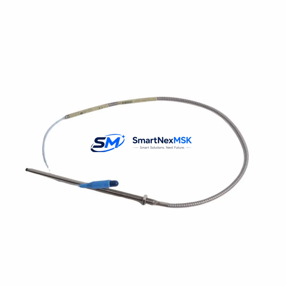
The Bently Nevada 330910-00-18-10-02-00 is an 8mm proximity transducer designed for the 3300 XL Series continuous machinery monitoring platform. As legacy 3300 XL installations age and original spare parts become increasingly difficult to source, this unit serves as a verified retrofit-ready replacement that preserves existing wiring topology, connector pinout, and signal conditioning compatibility. Whether you are managing a planned outage, responding to an unplanned sensor failure, or executing a broader control system modernization program, the 330910-00-18-10-02-00 is engineered to restore full monitoring capability with minimal intervention.
This transducer operates within the standard Bently Nevada proximity system architecture, pairing directly with the 3300 XL extension cable and the 3300 XL proximitor/driver module. The output signal — a DC voltage proportional to the gap between the probe tip and the observed target — is fully compatible with the 3300 XL monitor cards installed in your existing rack. No recalibration of the monitor card is required when replacing a like-for-like 8mm transducer within the same system series, provided the gap voltage is re-verified during commissioning.
Upgrade Compatibility Table
| Parameter | Detail |
|---|---|
| SKU / Part Number | 330910-00-18-10-02-00 |
| Series Compatibility | Bently Nevada 3300 XL Series |
| Probe Diameter | 8mm |
| Cable Length | 1.0m integral cable (pairs with 3300 XL extension cable) |
| Connector Type | Standard BN coaxial connector — direct replacement, no adapter required |
| Mounting Thread | M10 × 1 — compatible with existing probe holder and bracket |
| Signal Output | –24 VDC nominal bias; linear range compatible with 3300 XL proximitor |
| Target Material | Steel / 4140 alloy steel (standard); verify for non-ferrous targets |
| Communication / Interface | Analog voltage signal to 3300 XL monitor card — no protocol migration required |
| Replacement Recommendation | Direct drop-in for 330910-00-18-10-02-00; verify gap voltage after installation |
| Commissioning Focus | Gap voltage verification, cable routing, proximitor power confirmation |
| Warranty | 12 months from date of shipment |
Retrofit Planning for Existing Automation Systems
Successful retrofit of the 330910-00-18-10-02-00 into an operating plant begins well before the maintenance window opens. Engineers should first audit the existing 3300 XL rack configuration to confirm which monitor cards — such as the 3300/16 Dual Voting or 3300/20 Radial Vibration Monitor — are receiving signals from the affected channel. The proximitor driver module, typically a 3300 XL 8mm proximitor, must be confirmed operational before the new transducer is installed, as a failed proximitor will produce misleading gap voltage readings regardless of probe condition.
Extension cable integrity is a frequently overlooked factor in proximity system retrofits. The 3300 XL extension cable connecting the probe to the proximitor should be inspected for jacket damage, connector corrosion, and continuity. A degraded extension cable can introduce noise into the vibration signal and trigger false alarms on the monitor card, even when the transducer itself is new. If the extension cable is original to the installation and has not been replaced in the past decade, concurrent replacement is strongly recommended.
For installations where the 3300 XL rack also hosts a 3300/55 Keyphasor module, the phase reference signal must be verified independently after the proximity transducer is replaced. The Keyphasor channel is mechanically independent but shares the same rack backplane power distribution, and any disturbance to the rack during transducer replacement should be followed by a full channel verification sweep across all active monitor cards in the chassis.
In control cabinets where the 3300 XL system interfaces with a DCS or safety instrumented system via a 3500/92 Communication Gateway or a legacy Modbus RTU link, the communication link should be monitored during the replacement window to confirm that the monitor card does not generate spurious trip signals that propagate to the DCS logic solver. Coordinating with the DCS operator to place the affected channel in bypass mode prior to transducer removal is standard practice and eliminates the risk of a nuisance shutdown.
Where the plant is transitioning from a 3300 XL platform to a 3500 Series rack as part of a broader modernization program, the 330910-00-18-10-02-00 transducer remains compatible with 3500 Series proximitor modules, allowing the probe and extension cable to be retained while the rack, monitor cards, and communication infrastructure are upgraded. This phased approach — retaining field-mounted sensors while upgrading the rack — is a proven strategy for minimizing capital expenditure and reducing the scope of field rewiring during system migration.
Downtime Control During System Migration
Minimizing unplanned downtime during a proximity transducer replacement requires a structured pre-outage preparation protocol. Before the maintenance window, the replacement 330910-00-18-10-02-00 should be bench-tested using a portable proximitor and a calibrated target to confirm that the probe produces the correct gap voltage curve across the linear range. This pre-shipment functional test, which is included as part of our standard outgoing quality inspection, provides documented evidence that the unit is operational before it enters the plant.
During the replacement, the original program logic in the DCS or PLC controlling the machinery protection response should not be modified. The 3300 XL monitor card retains its configured alert and danger setpoints independently of the transducer, and these setpoints remain valid for the replacement probe provided the gap is set correctly. Technicians should use the original gap setting documentation — typically recorded during the initial commissioning of the machine — as the reference for the new installation. If original commissioning records are unavailable, the standard gap for an 8mm probe on a steel target is 1.0mm to 1.5mm, corresponding to approximately –10 VDC to –12 VDC bias voltage.
After the transducer is installed and the gap is set, the monitor card should be taken out of bypass and the channel observed for a minimum of 15 minutes at operating speed before the maintenance window is formally closed. Any deviation from the pre-outage baseline vibration trend should be investigated before returning the machine to full load. Retaining the original transducer as a tested spare — rather than discarding it — provides an additional layer of protection during the post-replacement observation period.
Retrofit Support FAQ
Q1: Is the 330910-00-18-10-02-00 a direct replacement for the original Bently Nevada part of the same number?
Yes. This unit is manufactured to the same dimensional, electrical, and performance specifications as the original Bently Nevada 330910-00-18-10-02-00. It uses the same M10 × 1 mounting thread, the same coaxial connector, and produces the same output voltage curve when paired with a 3300 XL 8mm proximitor. No modifications to the probe holder, extension cable, or monitor card configuration are required for a like-for-like replacement.
Q2: What commissioning steps are required after installation?
After mechanical installation, the gap voltage must be verified using the monitor card’s front-panel meter or a calibrated voltmeter at the proximitor output terminals. The gap should be adjusted until the bias voltage falls within the linear range specified for the 3300 XL 8mm system. The channel should then be observed at operating speed to confirm that the vibration amplitude and phase readings are consistent with the pre-replacement baseline trend data.
Q3: Can this transducer be used with a 3500 Series rack?
Yes. The 330910-00-18-10-02-00 is compatible with 3500 Series proximitor modules that support 8mm probe systems. This makes it suitable for phased migration projects where the field-mounted sensors are retained while the monitoring rack is upgraded from 3300 XL to 3500 Series hardware. Confirm the specific 3500 proximitor part number with your system documentation to ensure compatibility.
Q4: What does the 12-month warranty cover?
The 12-month warranty covers manufacturing defects in materials and workmanship from the date of shipment. Each unit undergoes outgoing quality inspection including functional testing prior to dispatch. Warranty claims are supported by our technical team at sales@smartnexmsk.com. Units damaged by incorrect installation, incorrect gap setting, or operation outside the specified electrical parameters are not covered under the warranty terms.
© 2026 SMARTNEXMSK. All rights reserved.
Original Source: https://smartnexmsk.com
Contact: sales@smartnexmsk.com | +86 18259474341


