Bently Nevada 330910-00-19-05-01-00 Retrofit-Ready Proximity Transducer for 3300 XL Control Systems
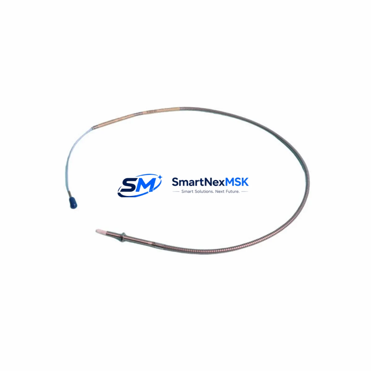
The Bently Nevada 330910-00-19-05-01-00 is an 8mm proximity transducer engineered for seamless integration into existing 3300 XL Series vibration monitoring systems. As legacy machinery protection infrastructure ages and OEM support windows close, this module provides a verified drop-in replacement path that preserves original wiring topology, signal conditioning parameters, and system calibration — minimizing retrofit risk and eliminating the need for full panel redesign.
Designed for rotating machinery protection in turbines, compressors, pumps, and gearboxes, the 330910-00-19-05-01-00 operates within the standard Bently Nevada proximity system architecture: transducer, extension cable, and Proximitor® sensor. When replacing a failed or end-of-life transducer in an existing 3300 XL installation, engineers must verify that the paired Proximitor® sensor — typically a 330180 or 330130 series unit — remains within its calibrated gap voltage range after substitution. The nominal gap voltage target of −10 VDC at 1.0 mm gap should be confirmed during commissioning using a calibrated oscilloscope or the system’s built-in gap voltage display on the 3500/40M or 3500/42M monitor modules.
Upgrade Compatibility Table
| Parameter | 330910-00-19-05-01-00 | Notes |
|---|---|---|
| Probe Diameter | 8 mm | Matches standard 3300 XL mounting bore |
| Cable Length | 5m integral cable | Verify extension cable compatibility (330130 series) |
| Thread | M10 × 1 | Confirm bracket thread before installation |
| Gap Range | 0.25 – 2.25 mm | Calibrate gap voltage post-installation |
| Frequency Response | DC – 10,000 Hz | Suitable for high-speed rotating machinery |
| Communication / Signal | Analog (eddy-current) | Compatible with 3500 Series rack monitors |
| Replacement Compatibility | Direct drop-in for 330910 series | Verify Proximitor® model pairing |
| Installation Requirement | Matched system (transducer + extension + Proximitor®) | Do not mix unmatched system components |
| Commissioning Check | Gap voltage, scale factor, OK relay status | Use 3500 rack front-panel display or System 1 software |
| Warranty | 12 Months | Covers manufacturing defects; includes pre-ship functional test |
Retrofit Planning for Existing Automation Systems
Retrofitting a 3300 XL proximity system requires a structured approach that accounts for the interdependencies between the transducer, extension cable, Proximitor® sensor, and the downstream monitor rack. In a typical 3500 Series rack installation, the 330910-00-19-05-01-00 transducer connects via a 330130-045-00-00 extension cable to a 330180-X1-05 Proximitor® sensor, which feeds the conditioned signal into a 3500/40M or 3500/42M monitor module housed in a 3500/05 or 3500/15 rack chassis.
Before removing the legacy transducer, engineers should document the existing gap voltage reading, OK relay status, and any active alarms in the System 1 condition monitoring software. This baseline ensures that post-installation verification can confirm the replacement transducer is performing within the original calibration envelope. If the existing extension cable shows signs of insulation degradation or connector corrosion, it should be replaced simultaneously — a 330130 series extension cable of matching length is the recommended pairing.
For control cabinets that also house a 3500/20 rack power supply module, verify that the total current draw after adding or replacing transducer channels remains within the rack’s rated capacity. In multi-channel installations where several 330910 series transducers are being replaced simultaneously, a phased replacement approach — one channel at a time — allows the process to remain in a monitored state throughout the retrofit window, reducing unplanned shutdown risk.
Where the existing installation includes a 3300/16 or 3300/20 monitor (older generation), migration to the 3500 Series rack architecture may be required to maintain full compatibility with current Bently Nevada firmware and System 1 software versions. In such cases, the 3500/05 rack, 3500/20 power supply, and appropriate I/O terminal blocks should be planned as part of the upgrade bill of materials. The 330910-00-19-05-01-00 transducer is fully compatible with both legacy 3300 and current 3500 Series signal conditioning chains, making it a low-risk anchor component in a phased migration strategy.
Field engineers should also confirm that the Keyphasor® module — typically a 3500/25 or 3500/26 — is correctly configured if the replacement transducer is installed on a shaft where phase reference is required for vector measurements. Incorrect Keyphasor® gap or polarity settings will produce erroneous 1X and 2X vibration vectors in the System 1 display, which can mask real machinery faults during the post-retrofit monitoring period.
Downtime Control During System Migration
Minimizing process downtime during a proximity transducer replacement requires pre-staging all replacement components — including the 330910-00-19-05-01-00 transducer, matched extension cable, and any required Proximitor® sensor — before the maintenance window opens. Each unit supplied by SMARTNEXMSK undergoes a pre-shipment functional test that verifies output voltage linearity, OK relay operation, and cable continuity, reducing the risk of discovering a defective component after the process has been shut down.
Where the process cannot be fully stopped, a bypass relay or temporary jumper on the 3500 rack’s OK relay output can allow the monitor channel to be taken out of service without triggering a full machinery trip. This approach must be coordinated with the site’s safety instrumented system (SIS) engineer and documented in the management of change (MOC) record before execution.
Original PLC logic and HMI faceplates referencing the vibration channel tag should be reviewed before the replacement transducer is commissioned. If the channel address or rack slot assignment changes during the retrofit — for example, when migrating from a 3300/16 to a 3500/40M — the corresponding tag in the DCS or PLC program must be updated to reflect the new Modbus or OPC-UA address. Failure to update the control program will result in the HMI displaying stale or invalid vibration data after the new transducer is energized.
Post-installation, a minimum 30-minute warm-up period should be observed before accepting gap voltage and vibration amplitude readings as stable. During this period, the 3500 rack’s front-panel OK LED and the System 1 channel status should be monitored continuously. Any OK relay dropout or gap voltage drift outside the ±0.5 VDC tolerance band indicates a wiring, gap setting, or component compatibility issue that must be resolved before returning the machinery to service.
Retrofit Support FAQ
Q1: Is the 330910-00-19-05-01-00 a direct replacement for all 330910 series variants?
The 330910-00-19-05-01-00 is a direct mechanical and electrical replacement for other 330910 series configurations sharing the same 8mm probe diameter and M10×1 thread. However, cable length and connector type must be verified against the specific variant being replaced. Consult the Bently Nevada 330910 series datasheet or contact SMARTNEXMSK for cross-reference confirmation before ordering.
Q2: What commissioning checks are required after installation?
After installation, verify the gap voltage at the Proximitor® output (target: −10 VDC ±1 VDC at nominal gap), confirm the OK relay is energized, and check that the 3500 rack channel displays a valid vibration amplitude in System 1. If a Keyphasor® is present, verify phase reference signal integrity before accepting the channel as commissioned.
Q3: Can this transducer be used with non-Bently Nevada signal conditioners?
The 330910-00-19-05-01-00 is optimized for use within the Bently Nevada matched proximity system (transducer + extension cable + Proximitor® sensor). Use with third-party signal conditioners is not recommended without independent calibration verification, as scale factor and OK relay thresholds are calibrated as a matched set.
Q4: What does the 12-month warranty cover?
The 12-month warranty covers manufacturing defects in materials and workmanship from the date of shipment. Each unit is functionally tested prior to dispatch. Warranty claims require return of the defective unit with a completed failure description. Physical damage, incorrect installation, or use outside specified environmental ratings are excluded. Contact sales@smartnexmsk.com to initiate a warranty claim.
© 2026 SMARTNEXMSK. All rights reserved.
Original Source: https://smartnexmsk.com
Contact: sales@smartnexmsk.com | +86 18259474341


