Bently Nevada 330910-00-21-10-02-00 3300 NSv Spare: Spare Replacement & Industrial Downtime Risk Control
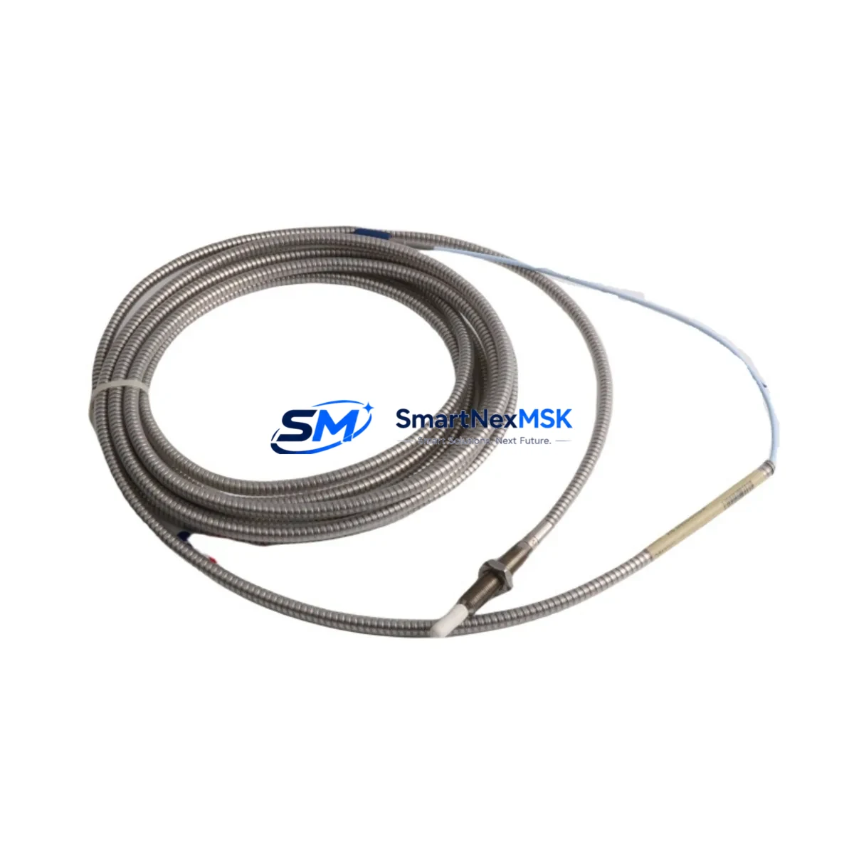
The Bently Nevada 330910-00-21-10-02-00 is an original 8mm eddy-current proximity probe engineered for the 3300 NSv vibration monitoring system. In rotating machinery protection environments — turbines, compressors, pumps, and gearboxes — this probe is a front-line component in continuous vibration surveillance. When it fails or degrades, the entire monitoring loop is compromised, leaving critical assets unprotected and exposing operations to unplanned downtime. Stocking a verified replacement is not optional; it is a fundamental element of any serious maintenance strategy.
For maintenance engineers managing predictive maintenance (PdM) programs, the 330910-00-21-10-02-00 sits at the intersection of mechanical and electrical reliability. Its eddy-current sensing principle requires no physical contact with the rotating shaft, making it inherently low-wear — but the probe tip, cable, and connector assembly are still subject to environmental degradation, chemical exposure, and mechanical vibration fatigue over time. Planned replacement intervals, typically aligned with major overhaul cycles, prevent the probe from becoming the weakest link in an otherwise robust monitoring chain.
Spare Maintenance Table
| Parameter | Specification |
|---|---|
| Part Number | 330910-00-21-10-02-00 |
| Brand | Bently Nevada |
| Series | 3300 NSv (Non-Standard Voltage) |
| Probe Type | 8mm Eddy-Current Proximity Probe |
| Sensing Range | 0–2 mm (standard linear range) |
| Output Sensitivity | –7.87 V/mm (–200 mV/mil) |
| Supply Voltage | –24 VDC (via 3300 XL driver/extension cable) |
| Cable Length | 2.1 m (probe + extension per suffix) |
| Temperature Range | –35°C to +177°C (probe tip) |
| Connector | Integral coaxial, armored cable |
| Compatibility | 3300 NSv Monitor, 3300 XL 8mm Driver, 3500/42M Module |
| Installation | Threaded mount, M10 × 1 thread, jam-nut secured |
| Application | Radial vibration, axial position, differential expansion |
| Maintenance Interval | Inspect every 12 months; replace per OEM schedule or on signal drift |
| Warranty | 12 Months |
| Condition | Original, tested before shipment |
Maintenance Planning for Continuous Operation
Replacing the 330910-00-21-10-02-00 in the field is rarely an isolated task. A disciplined maintenance engineer will treat the probe replacement as a trigger for a broader loop inspection. The 3300 XL 8mm Extension Cable (typically 5 m or 9 m, matched to the probe suffix) should be inspected for jacket cracking, connector corrosion, and continuity before the new probe is commissioned — a degraded extension cable will immediately compromise the calibrated output of a new probe.
The 3300 NSv Proximitor Sensor (driver module) mounted in the control cabinet should be verified for correct bias voltage output, typically –10.0 VDC ±0.5 V at the gap center. If the driver is out of specification, replacing only the probe will not restore system accuracy. In parallel, the 3500/42M Proximitor I/O Module in the 3500 rack should be checked for channel alarm setpoints, OK relay status, and any latched fault conditions that may have been triggered by the failed probe.
Within the control cabinet, the 3500 Rack Power Supply (3500/15 or 3500/05) should be confirmed to be delivering stable –24 VDC to the Proximitor channels. Voltage ripple or transient drops can cause false OK-relay trips and erroneous vibration readings even with a new probe installed. The 3500/20 Rack Interface Module and its communication link to the DCS or historian should also be verified to ensure that the restored channel data is being correctly transmitted upstream.
For plants running older 3300 series racks alongside newer 3500 infrastructure, the 3300/20 Rack Interface Module and associated 3300 Power Supply should be included in the inspection checklist. These legacy components are often overlooked during probe replacements but are common sources of intermittent faults in aging systems. Stocking a spare 3300/55 Dual Voting Logic Module alongside the proximity probe is a prudent strategy for facilities committed to extending the operational life of legacy 3300 installations.
Finally, the Keyphasor Module (3500/25 or 3300 Keyphasor) should be confirmed operational, as phase-referenced vibration analysis depends on a clean Keyphasor signal. Any degradation in the Keyphasor loop will affect the quality of 1× and 2× vibration data even after the proximity probe is successfully replaced.
Site Replacement Workflow
Step 1 — Isolation & Permit: Obtain a work permit and isolate the monitoring channel at the 3500 rack. Note the current gap voltage and vibration reading before disconnection to establish a baseline for post-installation verification.
Step 2 — Probe Removal: Loosen the jam nut and carefully back out the 330910-00-21-10-02-00 from the probe mount. Inspect the probe tip for impact damage, chemical deposits, or thread wear. Inspect the mounting boss for corrosion or thread damage that could affect the new probe’s gap setting.
Step 3 — Extension Cable Check: Disconnect the extension cable from the Proximitor driver. Measure cable resistance and check for shorts. Replace the extension cable if resistance is out of specification or if the connector shows signs of moisture ingress.
Step 4 — New Probe Installation: Thread the replacement 330910-00-21-10-02-00 into the mount. Set the gap to the OEM-specified value (typically 1.0 mm for 8mm probes) using a non-ferrous feeler gauge or by monitoring the bias voltage output at the driver. Torque the jam nut to specification and secure the cable routing to prevent vibration-induced fatigue.
Step 5 — System Verification: Reconnect the extension cable and restore power to the Proximitor channel. Confirm bias voltage is within the –10.0 VDC ±0.5 V window. Verify the OK relay is energized and that the 3500 rack is displaying a valid vibration reading. Clear any latched alarms and confirm the channel is communicating correctly to the DCS historian.
Step 6 — Documentation: Record the replacement date, new probe serial number, gap setting, and post-installation bias voltage in the plant maintenance management system (CMMS). Update the spare parts inventory to trigger reorder of a replacement unit, maintaining minimum stock levels for critical monitoring loops.
Spare Parts Support FAQ
Q: How do I confirm the 330910-00-21-10-02-00 is compatible with my existing 3300 NSv system?
A: The suffix structure of the 330910 series encodes probe length, cable length, and temperature rating. The suffix -00-21-10-02-00 specifies a standard 2.1 m probe-to-driver configuration. Verify your existing Proximitor driver model and extension cable length against the Bently Nevada 3300 NSv system documentation. If your rack uses a 3500/42M module, confirm the channel is configured for 8mm probe input. We recommend providing your existing probe part number and rack model when ordering to ensure a direct replacement.
Q: What is your pre-shipment testing process for this proximity probe?
A: Every 330910-00-21-10-02-00 unit is bench-tested for bias voltage output, sensitivity linearity, and OK-relay function before shipment. Units are shipped with a test report confirming electrical performance within OEM specification. Packaging includes anti-static protection and mechanical cushioning to prevent transit damage to the probe tip and connector.
Q: Can this probe replace older 330910 variants with different suffixes?
A: Direct suffix substitution requires careful verification. Different suffixes indicate different cable lengths, temperature ratings, or connector configurations. Substituting an incorrect suffix can result in calibration errors, gap-setting difficulties, or system OK-relay faults. We recommend consulting the Bently Nevada 3300 NSv compatibility matrix or contacting our technical team before substituting a different suffix variant.
Q: What is the warranty coverage and what does it include?
A: All units carry a 12-month warranty from the date of shipment, covering manufacturing defects and electrical performance failures under normal operating conditions. The warranty does not cover damage resulting from incorrect installation, mechanical impact, chemical exposure beyond the rated environment, or operation outside the specified supply voltage range. Warranty claims are supported with replacement or refund, subject to inspection of the returned unit.
© 2026 SMARTNEXMSK. All rights reserved.
Original Source: https://smartnexmsk.com
Contact: sales@smartnexmsk.com | +86 18259474341


