Bently Nevada 330910-16-23-10-02-00 Retrofit Proximity Probe: Compatible Upgrade for 3300 NSv Control Systems
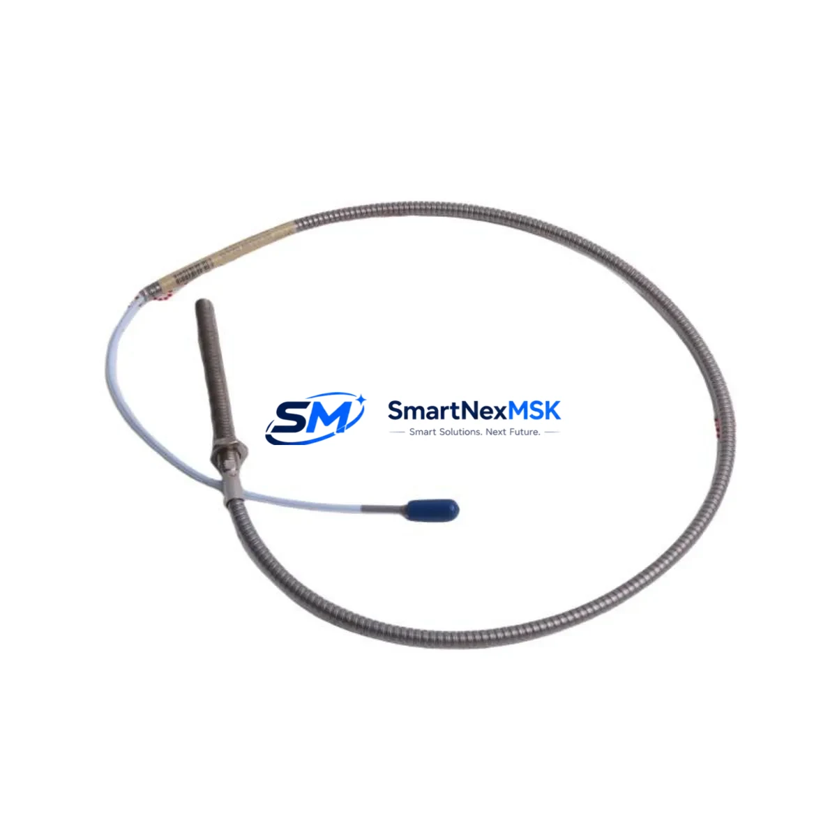
The Bently Nevada 330910-16-23-10-02-00 is a retrofit-ready proximity probe engineered for seamless integration into existing 3300 NSv Series vibration monitoring systems. As legacy Bently Nevada 3300 Series components reach end-of-life or become increasingly difficult to source, plant engineers and reliability teams face mounting pressure to maintain continuous machinery protection without triggering full-system overhauls. This probe is designed to address exactly that challenge — providing a verified drop-in replacement path that preserves your existing wiring infrastructure, rack architecture, and signal conditioning chain while delivering the measurement accuracy required for turbine, compressor, and pump protection applications.
Whether you are replacing a failed probe on a critical rotating machine, upgrading a legacy 3300 XL system to extend its service life, or consolidating spare parts inventory across multiple plant sites, the 330910-16-23-10-02-00 offers a reliable, field-proven solution backed by a 12-month warranty and pre-shipment functional testing.
Upgrade Compatibility Table
| Parameter | Details |
|---|---|
| SKU / Part Number | 330910-16-23-10-02-00 |
| Brand | Bently Nevada |
| Compatible Series | Bently Nevada 3300 NSv, 3300 XL, 3500 Series (with appropriate driver) |
| Probe Type | Eddy-Current Proximity Probe |
| Cable Length | 16 ft (approx. 5 m) — verify against existing installation |
| Connector Type | Standard Bently Nevada coaxial connector — direct replacement |
| Signal Output | -18 VDC nominal (compatible with 3300 NSv driver/monitor) |
| Installation Interface | Threaded tip mount — matches existing probe holder/bracket |
| Communication Compatibility | Analog signal chain; compatible with 3300 NSv monitor cards and 3500/22M proximity monitors |
| Replacement Recommendation | Direct replacement for worn, damaged, or discontinued 3300 NSv proximity probes |
| Commissioning Notes | Verify gap voltage at installation; recalibrate if replacing probe with different sensitivity |
| Warranty | 12 Months from date of shipment |
Retrofit Planning for Existing Automation Systems
Successful integration of the 330910-16-23-10-02-00 into a running plant begins well before the probe arrives on site. A structured retrofit plan reduces risk, shortens commissioning time, and protects the integrity of your machinery protection system.
Start by auditing the existing 3300 NSv monitor rack. Confirm that the installed 3300 NSv monitor cards — typically housed in a 3300/16 or 3300/20 rack — are configured for the correct probe sensitivity (7.87 mV/µm or 200 mV/mil). If the rack also contains 3300/55 tachometer input cards or 3300/46 temperature monitor cards, document their slot assignments before any physical work begins, as rack reconfiguration can affect channel addressing in the System 1 condition monitoring software.
Next, inspect the existing extension cable. The 330910-16-23-10-02-00 probe is designed to work with the standard Bently Nevada 330130 series extension cables. Confirm cable length and connector integrity. If the extension cable shows signs of insulation damage or connector corrosion — common in high-temperature or high-humidity environments — replace it simultaneously with the probe to avoid introducing a new fault source after installation.
For plants running a 3500 Series machinery protection system alongside legacy 3300 NSv equipment, verify that the 3500/42M or 3500/22M proximity monitor cards are configured to accept the probe’s output range. The 3500 Series Rack Configuration software (RCS) allows engineers to define probe type, scale factor, and gap voltage limits per channel — a critical step when mixing probe generations across a shared rack.
Terminal wiring should be verified against the original loop drawing. The coaxial signal path — probe body, extension cable, and driver/monitor input — must maintain shield continuity throughout. Any break in the shield ground path will introduce noise into the vibration signal, potentially triggering false alarms on the 3300 NSv monitor or corrupting trend data in the System 1 historian. Use a calibrated signal simulator such as the Bently Nevada 330180 proximitor simulator to verify the complete signal chain before returning the machine to service.
If the retrofit is part of a broader control cabinet upgrade — for example, migrating from a standalone 3300 NSv rack to an integrated 3500 Series cabinet with a 3500/01 rack interface module — plan for the migration of HMI display configurations as well. Operators accustomed to reading vibration trends on a legacy DCS faceplate will need updated tag mappings and alarm setpoints transferred to the new display environment. Coordinate with the DCS vendor to ensure that the 4–20 mA or Modbus RTU outputs from the new monitor cards are correctly mapped to the existing process historian tags.
Downtime Control During System Migration
Minimizing unplanned downtime during a proximity probe replacement is a primary concern for any reliability engineer. The 330910-16-23-10-02-00 is designed to support a rapid swap procedure that, when properly planned, can be completed within a single scheduled maintenance window.
Before isolating the machine, export the current vibration baseline data from System 1 or your plant historian. This provides a reference for post-installation comparison and supports the acceptance test report. If the 3300 NSv monitor is configured with a bypass relay — available on some 3300/16 rack configurations — activate the bypass before disconnecting the probe to prevent a spurious trip signal from reaching the turbine control system or emergency shutdown (ESD) logic.
During the physical swap, avoid bending the probe cable at the connector junction. The coaxial connector on the 330910-16-23-10-02-00 is rated for a defined number of mating cycles; excessive force or misalignment during installation can damage the center pin and introduce intermittent signal loss. Use the correct torque specification for the probe tip thread — typically finger-tight plus a quarter turn — and verify the air gap with a digital multimeter measuring the driver output voltage before closing the probe holder.
After installation, perform a static gap check and a dynamic signal verification using a portable vibration analyzer or the built-in diagnostic functions of the 3500/22M monitor. Compare the new probe’s gap voltage and sensitivity against the values recorded during the pre-shutdown baseline. If the readings fall within the expected range, the bypass relay can be deactivated and the machine returned to normal monitoring. Document the as-found and as-left gap voltages in the maintenance management system (CMMS) to support future predictive maintenance planning.
For multi-machine sites where several 3300 NSv probes are being replaced in a single outage, pre-stage all replacement probes and extension cables, pre-cut and label terminal wires, and assign a dedicated technician to each machine to run parallel replacement tasks. This approach can reduce total outage duration by 40–60% compared to sequential replacement.
Retrofit Support FAQ
Q1: Is the 330910-16-23-10-02-00 a direct drop-in replacement for my existing 3300 NSv proximity probe?
In most cases, yes. The 330910-16-23-10-02-00 shares the same connector type, cable length, and output sensitivity as the standard 3300 NSv proximity probe family. However, you should verify the probe tip thread size and the driver/monitor card sensitivity setting before installation. If your existing system uses a non-standard sensitivity (e.g., 100 mV/mil instead of 200 mV/mil), recalibration of the monitor card will be required after the swap.
Q2: What commissioning steps are required after installing this probe?
After physical installation, perform a static gap voltage check using a digital multimeter at the driver output terminals. The nominal gap voltage for a correctly installed 3300 NSv probe is typically between -10 VDC and -18 VDC depending on the set gap distance. Next, verify the dynamic signal by rotating the shaft slowly (if possible) or using a signal simulator to confirm that the monitor card is receiving a clean, noise-free signal. Finally, check alarm and trip setpoints in the monitor configuration and confirm that the System 1 or DCS tag is receiving updated data before releasing the machine to operations.
Q3: Can this probe be used with a Bently Nevada 3500 Series rack?
Yes, with the appropriate driver/monitor card configuration. The 3500/22M proximity monitor card supports the 3300 NSv probe family when configured with the correct probe type and scale factor in the 3500 Rack Configuration Software (RCS). Confirm the channel configuration before installation and perform a full functional test after wiring to ensure compatibility with the 3500 rack’s self-test and OK relay logic.
Q4: What does the 12-month warranty cover, and how is it supported?
The 12-month warranty covers manufacturing defects and functional failures under normal operating conditions from the date of shipment. Each unit undergoes pre-shipment functional testing to verify output sensitivity, connector integrity, and cable continuity. In the event of a warranty claim, contact our technical support team with the order reference and a description of the failure mode. Replacement units are dispatched from stock to minimize your system downtime.
© 2026 SMARTNEXMSK. All rights reserved.
Original Source: https://smartnexmsk.com
Contact: sales@smartnexmsk.com | +86 18259474341


