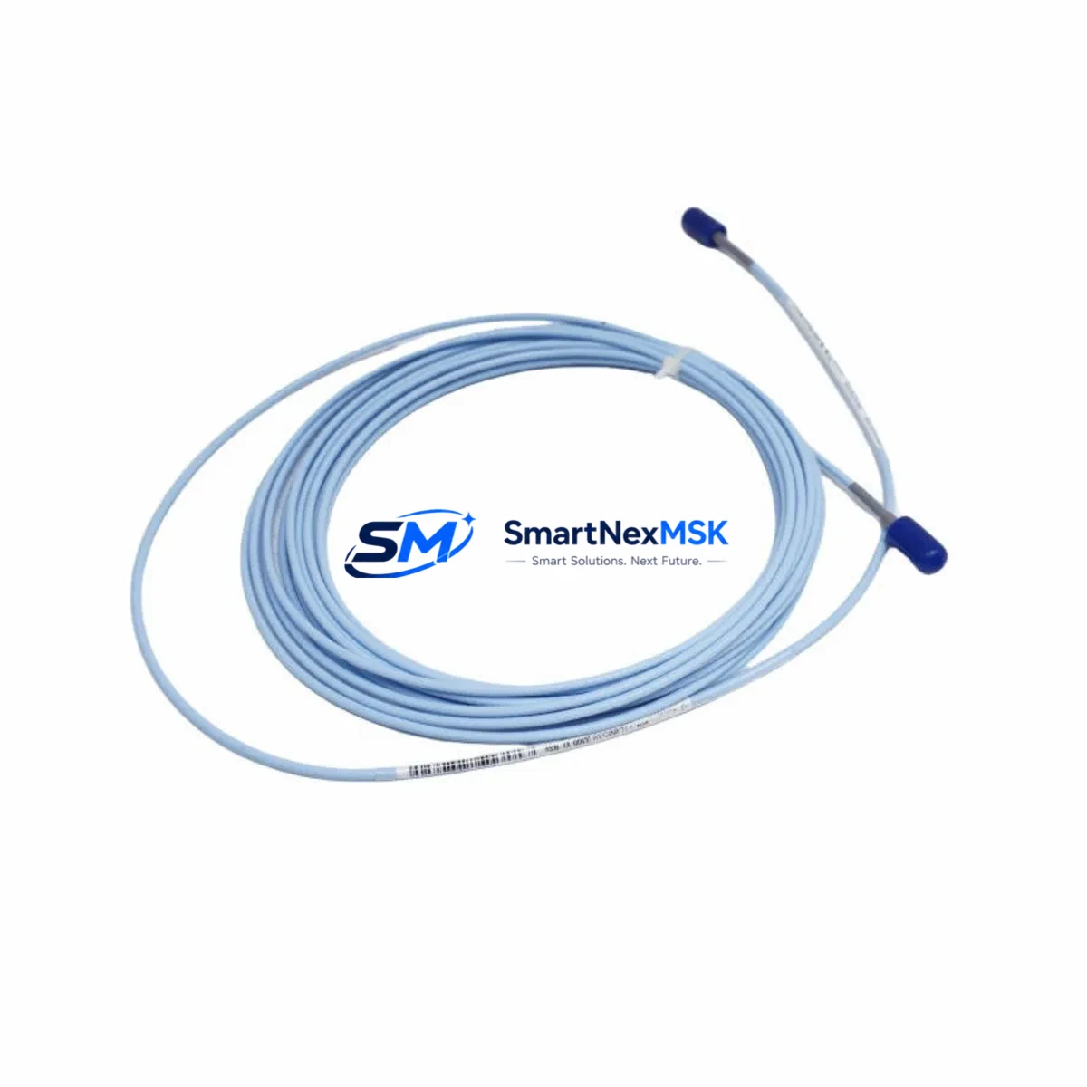
Bently Nevada 330930-045-04-CN Retrofit-Ready Proximity Transducer for 3300 XL Control Systems
The Bently Nevada 330930-045-04-CN is a high-precision eddy-current proximity transducer engineered for seamless integration into legacy 3300 XL Series vibration monitoring systems. As original OEM units reach end-of-life and spare-part availability tightens, this retrofit-ready replacement provides a verified drop-in upgrade path that preserves existing wiring, signal conditioning architecture, and machinery protection logic without requiring panel redesign or software re-engineering.
Designed for continuous operation in demanding industrial environments — including turbomachinery, compressor trains, steam turbines, and rotating equipment skids — the 330930-045-04-CN delivers the same 5 mm nominal gap range, 200 mV/mil (7.87 V/mm) sensitivity, and -18 VDC to -24 VDC supply voltage characteristics as the original NSv series transducer. Engineers performing condition monitoring upgrades or emergency replacements can install this unit with confidence that vibration, position, and speed measurement accuracy will be maintained across the full operating bandwidth.
Before committing to a retrofit, site engineers should verify several critical parameters. Power supply capacity at the junction box must support the transducer’s quiescent current draw alongside any co-located 3300 XL monitor cards such as the 3300/16 Dual Voting or 3300/20 Radial Vibration Monitor. Terminal wiring should be inspected for correct polarity on the coaxial extension cable — typically a 330130 or 330180 series armored cable — and the driver/oscillator unit, commonly a 330930 series proximitor, must be confirmed compatible with the replacement transducer’s target range and gap voltage curve.
Backplane interface and rack slot assignments within the 3500 Rack or legacy 3300 Rack should be documented before removal of the original transducer. Module address settings, DIP switch configurations on associated 3300/25 or 3300/46 I/O modules, and any hardwired relay trip setpoints must be recorded and preserved. Where the control system interfaces with a DCS via 4–20 mA analog output or Modbus RTU over RS-485, the signal scaling and engineering unit conversion factors should be validated post-installation to ensure the historian and alarm management system receive accurate process values.
HMI faceplate graphics linked to the vibration channel — whether running on a GE Cimplicity, Wonderware InTouch, or Rockwell FactoryTalk View platform — should be reviewed to confirm that tag names and I/O addresses remain unchanged after the transducer swap. In systems where the 3300 XL communicates with a safety instrumented system (SIS) via hardwired voting logic, the proof-test interval and bypass procedures must be followed in accordance with the site’s functional safety management plan.
Upgrade Compatibility Table
| Parameter | Original NSv (330930-045-04-CN OEM) | Retrofit Unit (330930-045-04-CN) |
|---|---|---|
| Nominal Gap Range | 5 mm (0–9 mm linear) | 5 mm (0–9 mm linear) |
| Sensitivity | 200 mV/mil (7.87 V/mm) | 200 mV/mil (7.87 V/mm) |
| Supply Voltage | -18 VDC to -24 VDC | -18 VDC to -24 VDC |
| Output Voltage Range | -2 VDC to -18 VDC | -2 VDC to -18 VDC |
| Connector Type | 3-pin MIL-C-5015 style | 3-pin MIL-C-5015 style (direct fit) |
| Cable Compatibility | 330130 / 330180 armored extension | 330130 / 330180 armored extension |
| Proximitor Compatibility | 330930 series driver/oscillator | 330930 series driver/oscillator |
| Rack Compatibility | 3300 Rack / 3500 Rack | 3300 Rack / 3500 Rack |
| Communication Protocol | 4–20 mA / Modbus RTU | 4–20 mA / Modbus RTU (no change) |
| Installation Requirement | Standard 1-inch NPT or M25 boss | Standard 1-inch NPT or M25 boss |
| Calibration Required | Gap voltage verification at site | Gap voltage verification at site |
| Warranty | OEM (expired / discontinued) | 12-Month Warranty |
Retrofit Planning for Existing Automation Systems
A successful retrofit of the 330930-045-04-CN into an operating plant begins well before the maintenance window opens. The engineering team should compile a complete bill of materials for the affected vibration monitoring loop, including the 330930 proximitor, the 330130-080-00-00 or 330180-X0-05 armored extension cable, the 3300/16 or 3300/20 monitor module seated in the 3300 Rack, and the associated 3300/46 I/O terminal board. Each component’s firmware revision and hardware revision should be logged, as certain 3500 Series monitor cards introduced revised gap voltage acceptance windows that may affect alarm setpoint calibration.
For plants running a hybrid architecture — where the 3300 XL coexists with a newer 3500/42M Proximitor I/O Module or a 3500/22M Transient Data Interface — the retrofit plan must account for the possibility that the replacement transducer’s output will feed both legacy and modern signal paths simultaneously. In such configurations, the 3500 Rack’s system power supply (typically a 3500/15 Power Supply module) should be load-checked to confirm adequate headroom for the additional transducer current draw.
Wiring adaptation is straightforward in most cases: the 330930-045-04-CN uses the same coaxial signal path and shield grounding convention as the original NSv unit, so the existing junction box terminal strip and cable gland arrangement can be reused without modification. However, if the plant has previously upgraded the proximitor to a 330930-045-00-CN or 330930-045-05-CN variant, the engineer should cross-reference the gap voltage curve to confirm that the replacement transducer’s linear range aligns with the installed proximitor’s calibration constants.
Where the vibration monitoring loop feeds a Triconex or Yokogawa ProSafe SIL-rated safety system via hardwired 4–20 mA, the retrofit team should coordinate with the SIS engineer to schedule a partial stroke test or bypass during the transducer swap. Communication links to the DCS historian — whether via OPC DA, OPC UA, or a legacy HART multiplexer — should be monitored during commissioning to confirm that the replacement transducer’s signal quality meets the historian’s scan-rate and quality-code requirements.
Downtime Control During System Migration
Minimizing unplanned downtime during a proximity transducer replacement requires a structured pre-outage preparation protocol. At least 48 hours before the maintenance window, the control room team should export a full backup of the 3300 XL monitor configuration using the System 1 Evolution software or the legacy System 1 v5.x configuration utility. This backup captures all channel assignments, alarm setpoints, trip multiply states, and Keyphasor reference channel assignments, ensuring that the replacement transducer can be commissioned against a verified baseline without relying on field-measured values alone.
During the swap, the affected vibration channel should be placed in bypass mode at the 3300/16 or 3300/20 monitor module to prevent a spurious trip from propagating to the machinery protection relay. If the plant’s safety management system requires a formal bypass authorization, this should be obtained and documented before the transducer is disconnected. The original transducer’s gap voltage should be recorded at the proximitor output terminal before removal, providing a reference value for the replacement unit’s initial gap-setting procedure.
After installing the 330930-045-04-CN, the gap voltage should be adjusted to the target value (typically -10.0 VDC ± 0.5 VDC for a 5 mm nominal gap) using a calibrated DC voltmeter at the proximitor output. Once the gap is confirmed, the channel bypass should be removed and the monitor’s OK relay status verified before returning the machinery to service. The entire swap — from isolation to bypass removal — can typically be completed within a two-hour maintenance window on a well-prepared site, preserving production continuity and avoiding extended shutdown costs.
Retrofit Support FAQ
Q1: Is the 330930-045-04-CN a direct drop-in replacement for the original Bently Nevada NSv proximity transducer in a 3300 XL system?
Yes. The 330930-045-04-CN maintains identical electrical specifications, connector geometry, and cable compatibility with the original NSv series transducer. No wiring modifications, proximitor recalibration, or monitor card reconfiguration are required beyond the standard gap-setting procedure performed after any transducer replacement.
Q2: What commissioning steps are required after installing the replacement transducer?
After mechanical installation, verify the gap voltage at the 330930 proximitor output terminal using a calibrated DC voltmeter. Adjust the transducer axial position until the output reads within the target range (typically -10.0 VDC ± 0.5 VDC for a 5 mm gap). Confirm the 3300/16 or 3300/20 monitor module’s OK LED is illuminated, check that vibration amplitude readings are within expected baseline values, and remove the channel bypass before returning the machine to service.
Q3: Will the replacement transducer affect existing HMI displays, DCS tag mappings, or historian data?
No. Because the 330930-045-04-CN is electrically identical to the original unit, the 4–20 mA output signal and Modbus RTU data values will remain within the same engineering unit range. HMI faceplate graphics, DCS I/O tag assignments, and historian trend configurations do not require modification. If the plant uses OPC UA or System 1 Evolution for condition monitoring, the channel will reappear with the same tag identity after the bypass is removed.
Q4: What warranty and pre-shipment testing does the replacement unit include?
Every 330930-045-04-CN unit undergoes functional testing prior to shipment, including gap voltage linearity verification across the full 0–9 mm measurement range and output impedance checks. The unit is supplied with a 12-month warranty covering manufacturing defects and electrical performance. A test report is available upon request. Units are packaged in anti-static, shock-protected enclosures and can be dispatched within 2–5 business days for standard orders.
© 2026 SMARTNEXMSK. All rights reserved.
Original Source: https://smartnexmsk.com
Contact: sales@smartnexmsk.com | +86 18259474341


