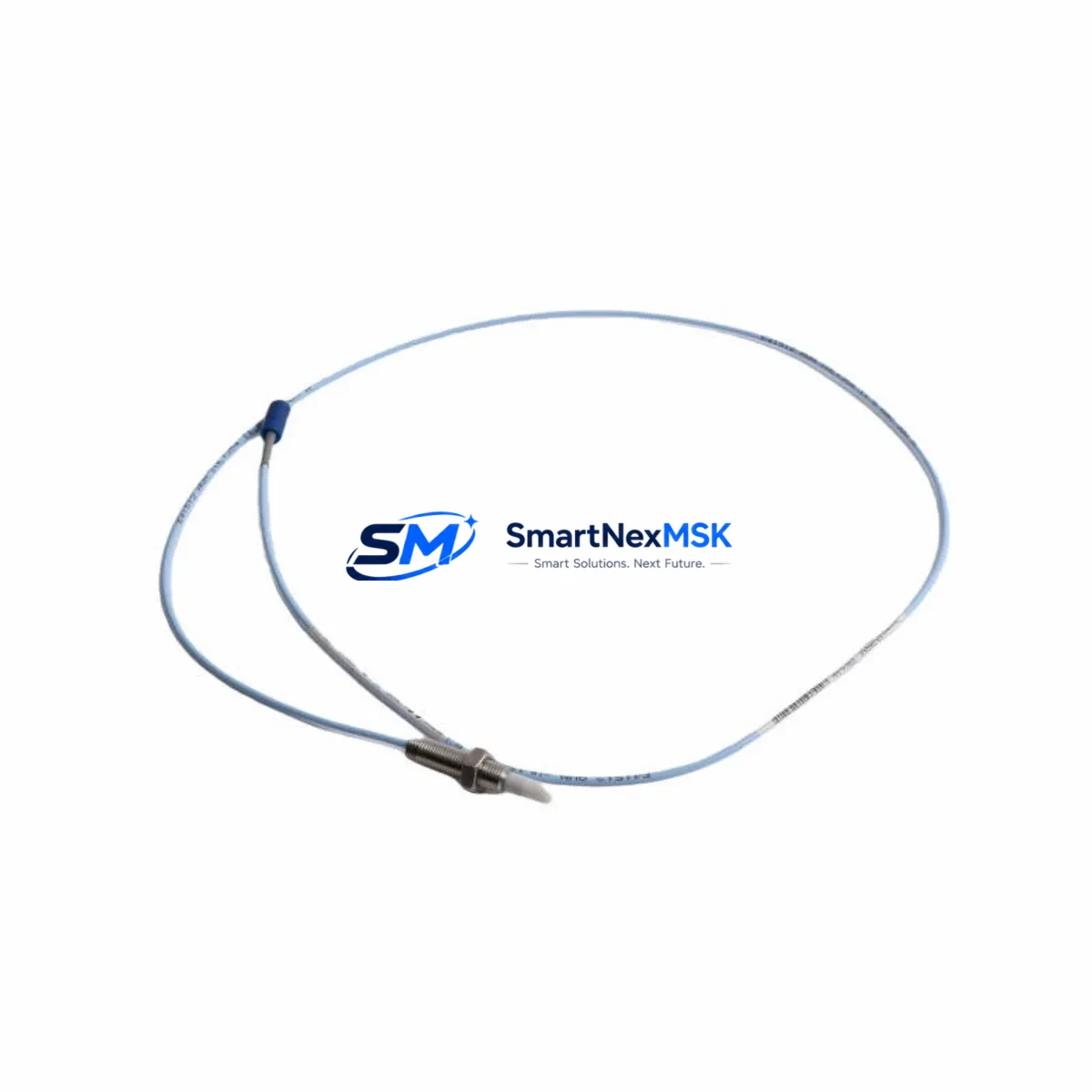
Bently Nevada 330930-060-01-00 Spare for 3300 XL NSv Automation
The Bently Nevada 330930-060-01-00 is an original eddy-current proximity transducer engineered for the 3300 XL NSv series vibration monitoring system. In rotating machinery protection environments — turbines, compressors, pumps, and gearboxes — this transducer is a critical front-line sensor. When it fails or degrades, the entire vibration monitoring loop is compromised, leaving rotating equipment unprotected and exposing the facility to unplanned shutdown risk. Maintaining a certified spare of the 330930-060-01-00 in your parts inventory is a fundamental element of any proactive maintenance strategy.
For maintenance engineers managing condition monitoring infrastructure, the 330930-060-01-00 delivers consistent gap voltage output, stable sensitivity, and reliable signal integrity across the full operating temperature range. Its compatibility with the 3300 XL NSv monitor and associated proximitor/extension cable assemblies makes it a direct replacement that requires no recalibration of the monitoring system when installed correctly. Procurement engineers can source this part with confidence: each unit is tested before shipment, backed by a 12-month warranty, and supported by long-term supply continuity.
Whether you are executing a planned turnaround, responding to a vibration alarm, or building a critical-spares inventory for an aging DCS or PLC-integrated machinery protection system, the 330930-060-01-00 is a proven, specification-matched replacement that minimises downtime and restores system integrity quickly.
Spare Maintenance Table
| Parameter | Specification / Detail |
|---|---|
| Part Number | 330930-060-01-00 |
| Brand | Bently Nevada |
| Series | 3300 XL NSv |
| Type | Eddy-Current Proximity Transducer |
| Cable Length | 5 ft (1.5 m) integral cable |
| Sensitivity | 200 mV/mil (7.87 V/mm) nominal |
| Operating Temperature | -35°C to +177°C (sensor tip) |
| Supply Voltage | -24 VDC (via proximitor/driver) |
| Output Range | -2 VDC to -18 VDC |
| Thread Size | 8 mm |
| Compatible Monitor | Bently Nevada 3300 XL NSv Series |
| Compatible Proximitor | 330180 Series, 330130 Series |
| Origin | USA |
| Application | Radial vibration, axial position, differential expansion monitoring |
| Installation | Direct replacement; verify gap voltage per OEM procedure |
| Warranty | 12 Months |
| Pre-shipment Test | Functional and output linearity verified before dispatch |
Maintenance Planning for Continuous Operation
When replacing the 330930-060-01-00 proximity transducer during a planned or emergency maintenance event, a thorough inspection of the surrounding measurement chain and control infrastructure is essential to prevent repeat failures and ensure the monitoring system is fully restored to specification.
Begin with the proximitor/driver module — typically a Bently Nevada 330180 or 330130 series unit — which conditions the transducer signal and provides the -24 VDC bias supply. A degraded proximitor can cause erratic gap voltage readings even with a new transducer installed. Inspect the extension cable assembly (commonly the 330130-080-00-00 or equivalent) for jacket damage, connector corrosion, and continuity; extension cable faults are a frequent root cause of transducer signal loss that is misdiagnosed as transducer failure.
At the monitor rack level, verify the 3300 XL NSv monitor module input card for alarm setpoint integrity and channel configuration. If the facility runs a Bently Nevada System 1 or 3500 series rack alongside the 3300 XL NSv, confirm that the rack power supply module is delivering stable -24 VDC and +5 VDC rails — power supply degradation is a common contributor to intermittent vibration channel faults. Check terminal block connections and field wiring for loose terminations, especially in high-vibration environments where mechanical loosening is accelerated.
For facilities integrating vibration data into a DCS or PLC via 4–20 mA output modules or Modbus/Profibus communication cards, confirm that the signal scaling and alarm relay outputs remain correctly configured after the transducer swap. If the machinery protection system feeds a safety instrumented system (SIS), coordinate with the SIS engineer to ensure the channel is properly bypassed and reinstated per the site safety management of change procedure.
Finally, inspect the junction box and field cable conduit for moisture ingress, which can cause insulation resistance degradation and introduce noise into the proximity measurement. A complete loop check — from transducer tip to monitor display — before returning the machine to service is the minimum acceptance criterion for any proximity transducer replacement.
Site Replacement Workflow
Step 1 — Isolation and Bypass: Notify the control room and place the affected vibration channel in bypass or inhibit mode on the 3300 XL NSv monitor to prevent spurious trips during the replacement procedure.
Step 2 — Transducer Removal: De-energise the proximitor supply, disconnect the extension cable at the junction box, and carefully unthread the 330930-060-01-00 from the probe holder. Record the original gap setting (typically expressed as a DC voltage, e.g., -10.0 VDC ±0.5 VDC for a standard 50 mil gap).
Step 3 — New Transducer Installation: Thread the replacement 330930-060-01-00 into the probe holder to the same depth as the original, or adjust to achieve the target gap voltage per the OEM specification sheet. Torque the locknut to the specified value to prevent vibration-induced loosening.
Step 4 — Loop Verification: Reconnect the extension cable, re-energise the proximitor, and measure the gap voltage at the monitor or proximitor output terminals. Confirm the reading is within the linear range and matches the expected value for the installed gap distance.
Step 5 — Alarm and Trip Setpoint Confirmation: Verify that the monitor’s alert and danger setpoints are correctly configured and that the channel is reading correctly on the System 1 or DCS historian before removing the bypass.
Step 6 — Return to Service: Remove the channel bypass, confirm normal vibration readings, and document the replacement in the maintenance management system (CMMS) with the new part serial number and gap voltage recorded.
This workflow is applicable whether replacing a failed transducer on an emergency basis or executing a scheduled replacement as part of a predictive maintenance programme. The 330930-060-01-00 is a direct, pin-compatible replacement for earlier 330930 series variants, simplifying the upgrade path for older 3300 series installations.
Spare Parts Support FAQ
Q1: Is the 330930-060-01-00 compatible with both the 3300 XL NSv and earlier 3300 series monitors?
The 330930-060-01-00 is designed and specified for the 3300 XL NSv series. It is generally compatible with earlier 3300 series monitors that use the same 8 mm eddy-current measurement chain, but compatibility should be confirmed against the specific monitor model’s input specification. Contact our technical team with your monitor model number for confirmation before ordering.
Q2: What is included in the 12-month warranty and pre-shipment testing?
Every 330930-060-01-00 unit is functionally tested for output linearity, sensitivity, and cable integrity before dispatch. The 12-month warranty covers manufacturing defects and performance deviations from the published specification under normal operating conditions. It does not cover damage resulting from incorrect installation, mechanical impact, or operation outside the specified temperature and voltage range.
Q3: How should I store the 330930-060-01-00 as a critical spare?
Store the transducer in its original packaging in a dry, temperature-controlled environment (10°C to 40°C) away from strong magnetic fields and mechanical shock. Inspect the connector and cable jacket annually. For long-term storage beyond 24 months, perform a bench test of gap voltage output before placing the unit in service to confirm the transducer has not degraded in storage.
Q4: Can you supply the complete 3300 XL NSv measurement chain as a kit?
Yes. We can supply the 330930-060-01-00 transducer together with the compatible extension cable assembly and proximitor module as a matched measurement chain kit, pre-tested as a system. This approach eliminates compatibility uncertainty and reduces installation time. Contact sales@smartnexmsk.com with your system configuration details for a kit quotation.
© 2026 SMARTNEXMSK. All rights reserved.
Original Source: https://smartnexmsk.com
Contact: sales@smartnexmsk.com | +86 18259474341


