Bently Nevada 330930-065-04-00 Spare for 3300 NSv Automation: Precision Replacement for Continuous Vibration Monitoring
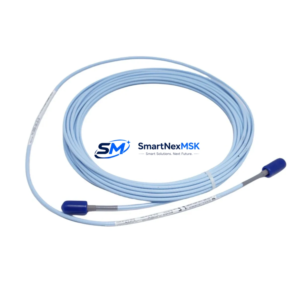
The Bently Nevada 330930-065-04-00 is an original armored coaxial extension cable engineered for the 3300 NSv proximity transducer system — one of the most widely deployed non-contacting vibration measurement platforms in rotating machinery protection. With a 65 cm active length and full OEM-specification shielding, this extension cable forms the critical signal path between the 3300 NSv proximity probe and its dedicated proximitor/driver module. Maintaining a verified spare in your parts inventory is essential for any facility operating turbines, compressors, pumps, or gearboxes under continuous vibration monitoring requirements.
For maintenance engineers and reliability teams, the extension cable is often the first component to degrade in high-vibration, high-temperature, or chemically aggressive environments. Armored jacket wear, connector corrosion, and signal attenuation from cable damage are leading causes of false trips and unplanned shutdowns. Stocking the 330930-065-04-00 as a ready-to-install spare eliminates the procurement lead time that turns a 2-hour cable swap into a multi-day outage.
Spare Maintenance Table
| Parameter | Specification |
|---|---|
| Part Number | 330930-065-04-00 |
| Brand | Bently Nevada |
| Series | 3300 NSv Proximity Transducer System |
| Type | Armored Coaxial Extension Cable |
| Cable Length | 65 cm (0.65 m) |
| Connector Type | MIL-C-5015 style, coaxial, gold-plated |
| Impedance | 50 Ω nominal |
| Operating Temperature | -35°C to +121°C |
| Compatibility | 3300 NSv Proximitor, 3300 XL 8mm Probe, 330730 / 330780 series probes |
| Application Environment | Turbines, compressors, pumps, gearboxes, rotating machinery |
| Installation | Direct OEM replacement; no recalibration required when matched with original probe and proximitor |
| Maintenance Recommendation | Inspect connectors and jacket annually; replace at first sign of attenuation or physical damage |
| Origin | USA (Bently Nevada / Baker Hughes) |
| Warranty | 12 Months |
Maintenance Planning for Continuous Operation
When replacing the 330930-065-04-00 extension cable during a planned outage or emergency intervention, a thorough maintenance engineer will treat the cable swap as an opportunity to audit the entire vibration monitoring loop. Begin by inspecting the mating 3300 NSv proximity probe (e.g., 330730-080-00-00 or 330780-50-00) for tip wear, thread damage, or contamination — a degraded probe will compromise signal quality even with a new cable installed. Verify the proximitor/driver module (such as the 3300/16 or 3300/20 series) for proper gap voltage output, typically –10 VDC ±0.5 V at the calibrated gap distance.
Check the 24 VDC or –24 VDC power supply feeding the proximitor for voltage stability and ripple; a noisy supply is a common source of spurious vibration alarms. Inspect terminal blocks and field wiring in the junction box for corrosion, loose terminations, or moisture ingress — particularly in outdoor or wash-down environments. If the system feeds into a 3500 Series rack, confirm that the 3500/42M or 3500/45 monitor module is reading correctly after cable replacement and that OK relay outputs are healthy.
For facilities running older 3300 Series racks alongside newer 3500 infrastructure, this is also an appropriate time to verify that signal conditioner cards, I/O terminal boards, and any interposing relay modules in the control cabinet are within calibration. Where the vibration signal is routed to a DCS or safety system via 4–20 mA output, check the signal isolator or barrier (such as a Pepperl+Fuchs or MTL type) for drift. Fuse holders and fuse ratings in the instrument power distribution panel should also be confirmed against the original design basis. If an HMI or operator workstation displays the vibration trend, verify that the tag scaling and alarm setpoints remain consistent after the cable replacement.
Maintaining a small buffer stock of the 330930-065-04-00 alongside matched probe tips and a spare proximitor module is considered best practice for any critical rotating machinery train. This approach supports a rapid mean-time-to-repair (MTTR) target and keeps the machinery protection system fully operational between scheduled turnarounds.
Site Replacement Workflow
Step 1 — Isolation & Permit: Obtain a work permit and confirm the machinery is in a safe state. De-energize the proximitor supply at the field junction box or instrument power panel before disconnecting any cable.
Step 2 — Document Existing Gap Voltage: Record the gap voltage displayed on the 3500/42M or equivalent monitor before removal. This baseline confirms the probe-to-target gap and will be used to verify correct reinstallation.
Step 3 — Remove the Faulty Cable: Disconnect the 330930-065-04-00 at both the probe connector and the proximitor input. Inspect both mating connectors for pin damage, corrosion, or contamination. Clean with isopropyl alcohol if required.
Step 4 — Install the Replacement Cable: Route the new 330930-065-04-00 following the original cable path. Avoid sharp bends below the minimum bend radius. Secure with original cable clamps or tie-wraps at the same support points to prevent vibration-induced fatigue at the connectors.
Step 5 — Re-energize & Verify: Restore power to the proximitor and confirm gap voltage returns to the previously recorded baseline (±0.5 V tolerance). Confirm the OK relay is energized and the monitor channel is not in alarm or bypass.
Step 6 — Functional Test & Documentation: Perform a functional check per the site maintenance procedure. Update the equipment history record with the replacement date, new cable serial/lot number, and post-installation gap voltage reading. Return the removed cable to the workshop for failure analysis if required.
This workflow is compatible with both hot-standby and single-train configurations and is designed to minimize downtime while maintaining full traceability for reliability-centered maintenance (RCM) programs.
Spare Parts Support FAQ
Q1: Is the 330930-065-04-00 compatible with both 3300 NSv and older 3300 XL probe systems?
The 330930-065-04-00 is designed and specified for the 3300 NSv system. While the connector format is physically similar to some 3300 XL configurations, compatibility must be verified against the specific probe and proximitor part numbers in your system. We recommend confirming the full transducer system loop (probe + extension cable + proximitor) before installation to ensure calibrated performance.
Q2: What pre-shipment testing is performed on this extension cable?
Each 330930-065-04-00 unit is inspected for connector integrity, cable continuity, insulation resistance, and impedance conformance prior to dispatch. Units are shipped with individual test records available on request. Packaging is designed to protect the connectors and armored jacket during international transit.
Q3: What does the 12-month warranty cover?
The 12-month warranty covers manufacturing defects, connector failure, and cable integrity under normal operating conditions as specified by Bently Nevada. It does not cover damage resulting from incorrect installation, mechanical abuse, or operation outside the rated temperature and environmental limits. Warranty claims are supported with replacement or credit at our discretion.
Q4: How should I manage long-term spare parts inventory for the 3300 NSv system?
For critical rotating machinery, we recommend maintaining a minimum of one matched set (probe + extension cable + proximitor) per monitored shaft as a ready-to-install spare. Extension cables should be stored in their original packaging in a clean, dry environment away from UV exposure and chemical vapors. Inspect stored spares annually for connector oxidation and replace any unit showing physical degradation before it enters service.
© 2026 SMARTNEXMSK. All rights reserved.
Original Source: https://smartnexmsk.com
Contact: sales@smartnexmsk.com | +86 18259474341


