Bently Nevada 3500/05-01-01-00-00-01 Retrofit-Ready 14-Slot Rack for 3500 Series Control Systems
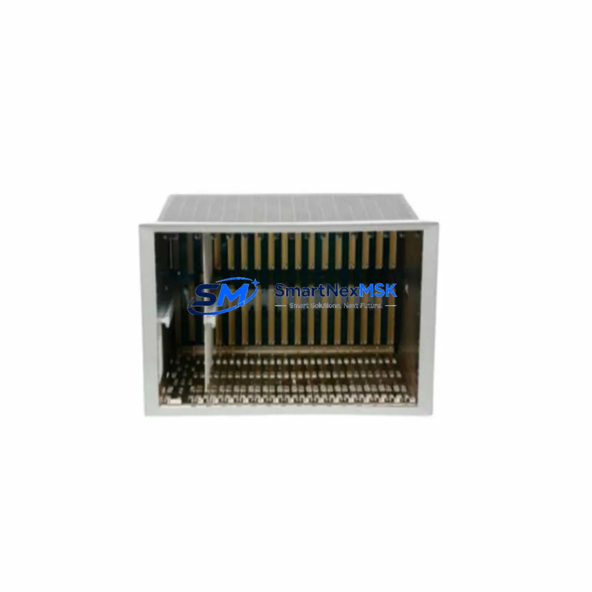
The Bently Nevada 3500/05-01-01-00-00-01 is a 14-slot rack designed as the structural and power backbone of the Bently Nevada 3500 Series Machinery Protection System. As aging plants face increasing pressure to modernize legacy vibration monitoring infrastructure, this rack serves as the critical starting point for any retrofit or upgrade project. Whether you are replacing a failed unit, expanding an existing 3500 chassis, or migrating from an older Bently Nevada 3300 or 7200 Series platform, the 3500/05-01-01-00-00-01 provides the physical and electrical foundation required for a smooth, low-risk transition.
In retrofit scenarios, engineers must first confirm that the replacement rack matches the original slot count and backplane interface. The 3500/05-01-01-00-00-01 accommodates up to 14 module positions, supporting a full complement of 3500 Series I/O and processing modules. Before installation, verify that your existing 3500/15-05-05-00 Power Supply Module delivers sufficient current capacity for the planned module configuration. Undersized power supply capacity is one of the most common causes of intermittent faults during rack replacement projects, particularly when adding new monitor modules such as the 3500/40M Proximitor/Seismic Monitor or the 3500/42M Proximitor/Seismic Monitor alongside legacy cards already in service.
Upgrade Compatibility Table
| Parameter | Details |
|---|---|
| Model | Bently Nevada 3500/05-01-01-00-00-01 |
| Slot Capacity | 14 Slots |
| Compatible Series | Bently Nevada 3500 Series Machinery Protection System |
| Backplane Interface | 3500 Series standard backplane bus |
| Power Supply Compatibility | 3500/15-05-05-00 and equivalent 3500 Series PSU modules |
| Communication Compatibility | Supports 3500/92 Communication Gateway Module (Modbus, Ethernet) |
| Replacement Path | Direct drop-in for 3500/05 rack variants; verify suffix codes for I/O configuration |
| Installation Requirement | Standard 19-inch rack mount; confirm DIN rail or panel mount adapter if applicable |
| Commissioning Note | Re-address module slots via System 1 or Rack Configuration Software after installation |
| Warranty | 12-Month Warranty — covers manufacturing defects and functional failures |
Retrofit Planning for Existing Automation Systems
A successful rack retrofit begins well before the physical swap. Start by documenting the current slot assignments of every installed module. In a typical 3500 Series installation, you may find a combination of the 3500/20 Keyphasor Module, 3500/25 Enhanced Keyphasor Module, 3500/40M Proximitor/Seismic Monitor, 3500/50M Tachometer Module, and 3500/60 Temperature Monitor occupying various positions. Each of these modules must be re-seated in the same logical slot position in the replacement rack to preserve the address mapping recognized by the host DCS or SCADA system.
Terminal wiring is another critical checkpoint. The 3500 Series uses a terminal block wiring scheme where field cables connect to I/O modules via dedicated terminal boards. Before pulling the old rack, photograph or document every terminal connection. Pay particular attention to the 3500/92 Communication Gateway Module, which handles Modbus RTU or Modbus TCP/IP communication to the plant DCS — typically a Honeywell Experion PKS, Emerson DeltaV, or ABB 800xA system. Any disruption to the gateway configuration will break the data link between the protection system and the control room, triggering nuisance alarms or loss of vibration data visibility.
If your plant is also upgrading from an older Bently Nevada 3300 Series or 7200 Series platform to the 3500 architecture, the rack replacement is only one element of a broader migration. You will also need to reconfigure transducer input ranges, update the 3500/92 gateway communication parameters, and revise any HMI faceplates in the operator workstation that reference the old tag structure. Coordinating these steps in advance — ideally during a planned shutdown window — is essential to keeping downtime within acceptable limits.
For plants running Bently Nevada System 1 software, the rack configuration file must be updated to reflect the new rack serial number and any changes to module population. This step is frequently overlooked during emergency replacements and can result in the protection system operating in bypass mode until the configuration is reconciled. Ensure your commissioning engineer has access to the original rack configuration backup before beginning the swap.
Downtime Control During System Migration
Minimizing unplanned downtime during a rack replacement requires a structured pre-outage preparation plan. Begin by exporting the full rack configuration from Bently Nevada System 1 or the Rack Configuration Utility at least 48 hours before the scheduled maintenance window. This backup preserves all channel setpoints, alarm thresholds, OK limits, and transducer scale factors that would otherwise need to be re-entered manually — a process that can add several hours to an already tight maintenance schedule.
During the physical swap, keep the 3500/15-05-05-00 Power Supply Module energized for as long as safely possible to maintain the Keyphasor reference signal to any connected machinery. Loss of the Keyphasor signal during a running machine coast-down can trigger spurious vibration alarms that propagate to the DCS and require manual acknowledgment before the system can be returned to normal operation. Where process safety permits, consider using a temporary bypass jumper on the 3500/20 Keyphasor Module output to hold the reference signal stable during the transition.
After the new 3500/05-01-01-00-00-01 rack is installed and all modules are re-seated, perform a full channel-by-channel functional verification before re-enabling protection. Use a calibrated signal simulator to inject test signals at each transducer input and confirm that the 3500 Series monitor modules respond correctly. Verify that the 3500/92 Communication Gateway Module has re-established its Modbus link to the DCS and that all vibration, position, and temperature tags are updating correctly in the operator HMI. Only after this verification is complete should the protection system be returned to active monitoring mode.
Retrofit Support FAQ
Q1: Is the 3500/05-01-01-00-00-01 a direct drop-in replacement for other 3500/05 rack variants?
A: The 3500/05-01-01-00-00-01 is compatible with other 3500/05 rack variants in terms of physical dimensions and backplane interface. However, the suffix codes in the part number indicate specific configuration options such as I/O orientation and termination style. Always cross-reference the full part number suffix against your existing rack documentation before ordering to confirm a direct drop-in fit.
Q2: What commissioning steps are required after installing the replacement rack?
A: After physical installation, re-load the saved rack configuration file via Bently Nevada System 1 or the Rack Configuration Utility. Verify module slot addresses, re-confirm all channel setpoints and alarm thresholds, and perform a functional signal test on each I/O channel. Re-establish the Modbus communication link via the 3500/92 gateway and confirm all DCS tags are updating correctly before returning the system to active protection mode.
Q3: Can I use this rack with both older and newer 3500 Series monitor modules?
A: Yes. The 3500/05-01-01-00-00-01 backplane is compatible with the full range of current 3500 Series monitor modules, including the 3500/40M, 3500/42M, 3500/50M, and 3500/60. If you are mixing older and newer module revisions, verify firmware compatibility via the Bently Nevada module compatibility matrix to avoid communication conflicts on the backplane bus.
Q4: What does the 12-month warranty cover?
A: The 12-month warranty covers manufacturing defects and functional failures under normal operating conditions. Each unit undergoes pre-shipment functional testing to verify backplane integrity, power distribution, and slot connectivity. Warranty claims are supported by SMARTNEXMSK with direct technical assistance. Contact sales@smartnexmsk.com for warranty registration and support.
© 2026 SMARTNEXMSK. All rights reserved.
Original Source: https://smartnexmsk.com
Contact: sales@smartnexmsk.com | +86 18259474341


