Bently Nevada 3500/22M 288055-01 Retrofit-Ready RTD/TC I/O for 3500 Series Control Systems
The Bently Nevada 3500/22M 288055-01 is a dual-channel RTD and Thermocouple Temperature I/O Module engineered for the Bently Nevada 3500 Series machinery protection platform. As legacy 3500 Series installations age and OEM support windows close, this module serves as the definitive retrofit-ready replacement — enabling engineers to restore full temperature monitoring capability without redesigning the rack architecture, rewriting monitor configuration software, or replacing the 3500 rack backplane.
Whether you are recovering from an unplanned module failure, executing a planned spare-parts refresh, or modernizing a turbine protection panel that has been in continuous service for over a decade, the 3500/22M 288055-01 slots directly into the existing 3500 rack and communicates natively over the internal rack bus. No firmware bridge, no protocol converter, and no HMI screen remapping is required when replacing a like-for-like unit.
Upgrade Compatibility Table
| Parameter | Details |
|---|---|
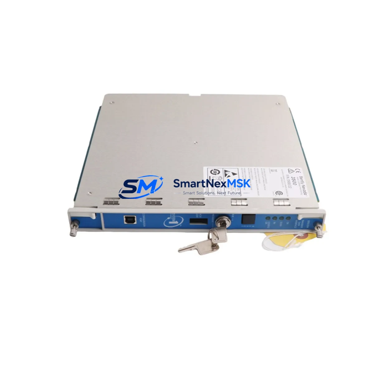
| SKU / Part Number | 3500/22M 288055-01 |
| Brand / OEM | Bently Nevada (Baker Hughes) |
| Compatible Platform | Bently Nevada 3500 Series Machinery Protection System |
| Module Slot Type | Standard 3500 rack slot (2-slot wide I/O module) |
| Backplane Interface | 3500 Series internal rack bus — direct plug-in, no adapter |
| Input Channels | Dual-channel RTD / Thermocouple temperature inputs |
| Communication Compatibility | Native 3500 rack bus; compatible with 3500/20 Communication Gateway for Modbus, Ethernet/IP, and OPC-DA integration |
| Replacement Targets | 288055-01 (same SKU), earlier 3500/22 revisions where pin-out is compatible |
| Installation Requirement | Power down rack slot before insertion; verify rack power supply (3500/15 or 3500/15E) capacity before adding module |
| Configuration Tool | System 1 / Rack Configuration Software (RCS) — existing configuration file can be reloaded after module swap |
| Debugging Focus | Verify channel OK status in RCS; confirm thermocouple type selection matches field wiring; check terminal block torque spec |
| Warranty | 12-Month Warranty — covers manufacturing defects and functional failure under normal operating conditions |
Retrofit Planning for Existing Automation Systems
A successful retrofit of the 3500/22M 288055-01 begins well before the module arrives on site. The first step is a rack audit: confirm the 3500 rack backplane slot assignment and verify that the adjacent modules — typically a 3500/32 4-Channel Relay Module or a 3500/42M Proximitor/Seismic Monitor — are not occupying the target slot or sharing a terminal block that would be disturbed during removal.
Next, review the power budget. The 3500/15 Power Supply Module or its enhanced variant, the 3500/15E, must have sufficient headroom to support the 3500/22M without tripping the rack’s internal power fault relay. If the rack is already near capacity — common in dense turbine protection panels where a 3500/40M Proximitor Monitor and multiple 3500/50 Tachometer Modules are installed — a power audit using the rack configuration software is mandatory before insertion.
Terminal wiring is the next critical checkpoint. The 3500/22M uses a standard 3500 I/O terminal block (ordered separately as part of the 3500/22M terminal block assembly). Confirm that the existing field wiring — typically 2-wire or 3-wire RTD leads or thermocouple extension cable — is correctly landed on the terminal block and that the thermocouple type (J, K, T, E, R, S, or B) is correctly selected in the Rack Configuration Software. A mismatch between the field thermocouple type and the software configuration is the most common commissioning error on this module.
For sites integrating the 3500 rack into a broader DCS or SCADA environment, verify the 3500/20 Communication Gateway Module configuration. If the plant historian or DCS — such as a Honeywell Experion PKS or an Emerson DeltaV controller — is polling temperature data via Modbus TCP or OPC-DA, confirm that the gateway’s tag mapping still references the correct rack slot address after the module swap. In some configurations, a slot change triggers a tag offset that must be corrected in the gateway’s communication configuration before the historian resumes logging.
Finally, if the 3500 rack is connected to a System 1 Evolution asset management platform, re-synchronize the rack configuration after the module swap to ensure that alarm setpoints, danger limits, and channel descriptions are correctly inherited by the replacement module. Do not rely on the previous module’s non-volatile memory — always reload the configuration from the System 1 database or a saved RCS backup file.
Downtime Control During System Migration
Minimizing downtime during a 3500/22M module swap requires a structured pre-outage preparation protocol. Before the maintenance window opens, export the full rack configuration from the Rack Configuration Software and save it to a secure engineering workstation. This file contains all channel configurations, alarm setpoints, thermocouple type assignments, and communication parameters — it is your recovery baseline if the new module requires a full reconfiguration.
During the swap, place the affected channels in bypass mode within the 3500 rack to prevent spurious trips from propagating to the 3500/32 Relay Module and triggering an unplanned shutdown of the protected machine. Confirm bypass status on the front-panel LED of the relay module before removing the 3500/22M from the rack slot.
After insertion of the replacement 3500/22M 288055-01, reload the saved configuration file via RCS, verify channel OK status for both temperature channels, and confirm that the process values displayed in the System 1 or DCS historian match the field thermocouple readings within the expected tolerance. Only then should bypass mode be removed and the channels returned to active protection. A typical like-for-like module swap following this protocol can be completed within a 30–45 minute maintenance window, keeping turbine or compressor downtime to an absolute minimum.
Retrofit Support FAQ
Q1: Is the 3500/22M 288055-01 a direct drop-in replacement for earlier 3500/22 revisions?
In most cases, yes. The 3500/22M is mechanically and electrically compatible with the standard 3500 rack slot. However, confirm the terminal block part number and wiring diagram against your existing installation before ordering, as some early 3500/22 revisions used a different terminal block assembly. Our team can assist with cross-reference verification prior to shipment.
Q2: Can I reload my existing Rack Configuration Software file onto the new module?
Yes. The 3500/22M 288055-01 accepts configuration files created in the Bently Nevada Rack Configuration Software. After inserting the module and powering up the rack slot, connect the RCS laptop via the rack’s front-panel serial or USB port and download the saved configuration. Verify channel OK status and alarm setpoints after download before returning the channels to active protection.
Q3: What field wiring checks are required before commissioning?
Verify thermocouple type selection in RCS matches the field thermocouple (J, K, T, E, R, S, or B). Confirm terminal block torque to the specified value in the 3500/22M installation manual. Check for continuity and correct polarity on thermocouple extension cables. For RTD inputs, verify 2-wire or 3-wire configuration matches the software channel setup. Inspect the terminal block for corrosion or loose leads, particularly on installations that have been in service for more than five years.
Q4: What does the 12-month warranty cover?
All 3500/22M 288055-01 units supplied by SMARTNEXMSK carry a 12-month warranty covering manufacturing defects and functional failure under normal operating conditions. Each unit undergoes pre-shipment functional testing to verify channel response, communication integrity, and power consumption within specification. Warranty claims are processed directly through our technical support team. Units showing damage from incorrect installation, overvoltage, or field wiring errors are evaluated on a case-by-case basis.
© 2026 SMARTNEXMSK. All rights reserved.
Original Source: https://smartnexmsk.com
Contact: sales@smartnexmsk.com | +86 18259474341


