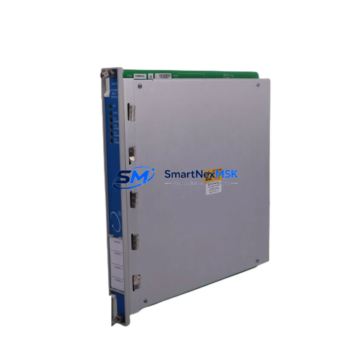
Bently Nevada 3500/32 125712-01 Spare for 3500 Automation
The Bently Nevada 3500/32 125712-01 is a 4-channel relay output module designed for the 3500 Series machinery protection system — one of the most widely deployed condition monitoring platforms in rotating equipment facilities worldwide. When this module fails or degrades, the consequences extend beyond a single I/O channel: relay-driven shutdown logic, alarm annunciation, and trip relay circuits may all be compromised, placing turbines, compressors, pumps, and other critical rotating assets at risk of unmonitored operation.
Sourced as an original spare, the 3500/32 125712-01 is fully compatible with the 3500 rack architecture and integrates directly with the 3500/20 rack interface module and 3500/15 power supply module without firmware reconfiguration. Each unit shipped by SMARTNEXMSK undergoes pre-shipment functional verification, including relay contact continuity, coil energization response, and output signal integrity checks, backed by a 12-month warranty from date of delivery.
Spare Maintenance Table
| Parameter | Specification |
|---|---|
| Part Number | 3500/32 125712-01 |
| Brand | Bently Nevada |
| Series | 3500 Machinery Protection System |
| Module Type | 4-Channel Relay Output Module |
| Output Channels | 4 independent relay outputs |
| Relay Contact Rating | Typically 2A @ 30 VDC / 0.5A @ 125 VAC (per 3500 Series spec) |
| Rack Compatibility | Bently Nevada 3500 Series rack (3500/20 interface required) |
| Power Supply Compatibility | 3500/15 Power Supply Module |
| Installation | Direct rack insertion, no tools required |
| Operating Temperature | 0°C to 65°C (standard industrial environment) |
| Application Environment | Turbine, compressor, pump, and fan protection systems |
| Condition | Original spare, pre-shipment tested |
| Warranty | 12 months from delivery date |
| Origin | USA |
Maintenance Planning for Continuous Operation
Maintenance engineers managing 3500 Series racks should treat the 3500/32 125712-01 as a critical spare in any rotating equipment protection cabinet. When planning a relay output module replacement, the surrounding system components must be inspected concurrently to avoid repeat failures and ensure the protection logic is fully restored.
Begin with the 3500/15 Power Supply Module — relay output modules are sensitive to supply voltage ripple, and a degraded power supply can cause intermittent relay chatter or false trips. Inspect the 3500/20 Rack Interface Module for communication faults, as relay output commands are routed through the rack backplane and any backplane connector corrosion will affect relay response latency.
Review the 3500/40M Proximitor/Seismic Monitor and 3500/42M Proximitor/Seismic Monitor channels feeding alarm and trip signals into the relay output module — if the relay module has failed due to sustained overcurrent, the upstream monitor channels should be checked for signal anomalies. Inspect 3500/22M Transient Data Interface configurations to confirm that trip multiply and inhibit logic has not been inadvertently altered during the fault period.
For wiring integrity, verify terminal block connections on the relay output wiring — loose or corroded terminals on the field-side relay wiring are a common cause of relay module stress. If the cabinet includes signal isolators between the 3500 relay outputs and the DCS or safety system, inspect isolator output continuity and isolation resistance. Check any fuse holders or circuit breakers protecting the relay output field circuits, as a sustained short on a relay output field circuit can cause module damage before the relay contact opens.
For facilities running extended maintenance intervals, consider stocking the 3500/32 125712-01 alongside the 3500/15 power supply and 3500/20 rack interface as a minimum viable spare set for the 3500 rack. This three-module combination covers the most common failure modes in 3500 Series installations and enables full rack restoration within a single maintenance window.
Site Replacement Workflow
Replacing the 3500/32 125712-01 in a live 3500 rack requires a structured approach to minimize downtime and avoid inadvertent trip events during the swap:
Step 1 — Pre-replacement inhibit: Place the affected relay output channels in inhibit mode via the 3500 rack configuration software (System 1 or Rack Configuration Software) to prevent spurious trips during module removal.
Step 2 — Document relay assignments: Record the current relay output assignments, trip multiply settings, and alarm setpoints from the rack configuration before removing the module. This data is essential for post-replacement verification.
Step 3 — Module removal: Power down the rack slot if the rack design permits hot-swap inhibit, then extract the 3500/32 module by releasing the front-panel locking mechanism. Inspect the backplane connector pins for damage or contamination.
Step 4 — Install replacement module: Insert the 3500/32 125712-01 replacement unit, ensuring full backplane engagement. The module does not require firmware flashing — configuration is stored in the rack and automatically applied upon insertion.
Step 5 — Verify relay outputs: Using the rack configuration software, force each relay output channel and confirm field-side continuity with a multimeter or loop tester. Verify alarm and trip relay contacts operate within specified response times.
Step 6 — Remove inhibit and return to service: Remove channel inhibits, confirm system status is normal, and document the replacement in the maintenance management system (CMMS) with the new module serial number and warranty start date.
This workflow is compatible with both planned maintenance windows and emergency replacement scenarios, and has been validated for use with 3500 Series racks in turbine, compressor, and pump protection applications.
Spare Parts Support FAQ
Q1: Is the 3500/32 125712-01 a direct drop-in replacement for older 3500/32 variants?
Yes. The 125712-01 revision is backward compatible with the 3500 rack architecture. Configuration is rack-resident, so no firmware changes are required. Always verify the rack configuration software version is current before replacement to ensure full feature compatibility.
Q2: How does SMARTNEXMSK verify the module before shipment?
Each 3500/32 125712-01 unit undergoes relay contact continuity testing, coil energization verification, and visual inspection for connector and PCB integrity. A test report is available upon request. The 12-month warranty covers functional failure under normal operating conditions from the date of delivery.
Q3: What is the recommended inventory strategy for 3500 Series relay output modules?
For facilities with multiple 3500 racks, we recommend maintaining at least one 3500/32 spare per rack cluster. Given the module’s role in trip and alarm relay logic, a failed relay output module can disable protection for multiple machine trains simultaneously. Pairing the relay output module spare with a 3500/15 power supply spare provides coverage for the two most common rack failure modes.
Q4: Can this module be used in safety-instrumented systems (SIS)?
The 3500/32 125712-01 is a machinery protection relay output module and is not SIL-rated for use as a primary safety function in IEC 61511-compliant SIS applications. For SIS relay output requirements, consult your functional safety engineer. However, the module is widely used in conjunction with SIS systems for alarm annunciation and non-safety trip relay functions.
© 2026 SMARTNEXMSK. All rights reserved.
Original Source: https://smartnexmsk.com
Contact: sales@smartnexmsk.com | +86 18259474341


