Bently Nevada 3500/33 149986-01 Maintenance-Ready Spare for 3500 Automation
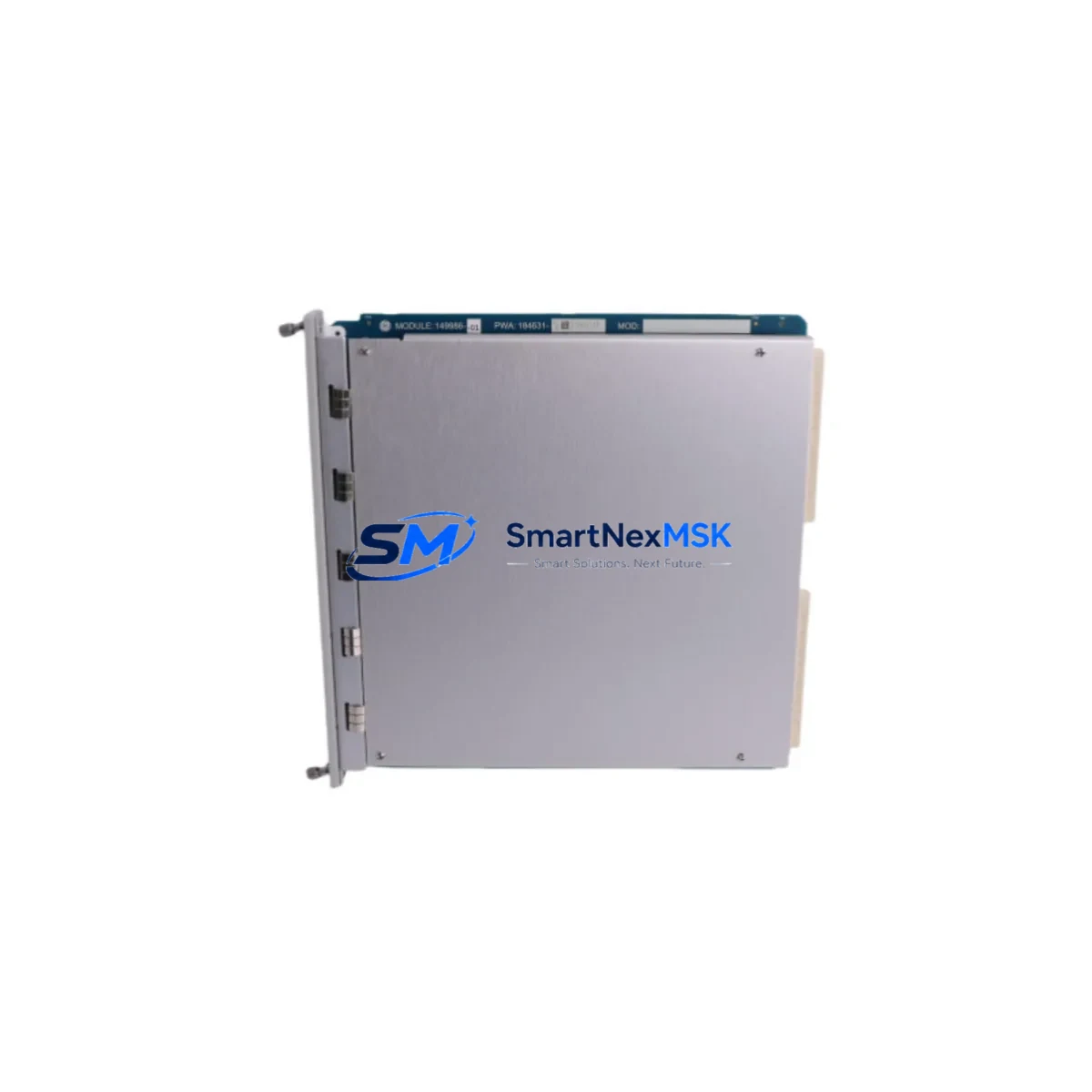
The Bently Nevada 3500/33 149986-01 is a 16-channel relay output module engineered for the 3500 Series Machinery Protection System — one of the most widely deployed continuous vibration monitoring platforms in rotating equipment facilities worldwide. For maintenance engineers managing turbines, compressors, pumps, and generators, this module is a mission-critical component in the relay output rack that drives alarm annunciation, trip logic, and protective shutdown sequences. When this module fails or degrades, the entire protection chain for the associated machine train is compromised, making rapid, verified spare replacement the only acceptable recovery path.
This listing supplies an original Bently Nevada 3500/33 149986-01 relay output module — not a clone, not a remanufactured substitute — sourced through established industrial distribution channels. Each unit undergoes pre-shipment functional verification against 3500 Series rack communication and relay actuation specifications before dispatch. A 12-month warranty covers all units from the date of delivery, providing procurement engineers with the documentation trail required for maintenance budget justification and asset lifecycle records.
Spare Maintenance Table
| Parameter | Specification / Value |
|---|---|
| Part Number | 149986-01 |
| Module Designation | 3500/33 |
| Series Compatibility | Bently Nevada 3500 Series Machinery Protection System |
| Module Type | 16-Channel Relay Output Module |
| Output Channels | 16 relay outputs (configurable alarm / trip) |
| Relay Contact Rating | Typically 5 A @ 250 VAC / 30 VDC (per 3500 Series spec) |
| Rack Slot Compatibility | 3500 Series standard rack (I/O slot) |
| Communication Interface | Internal rack backplane bus |
| Power Supply Requirement | Supplied via 3500/15 or 3500/15E Power Supply Module |
| Operating Temperature | 0 °C to 60 °C (standard industrial enclosure) |
| Mounting | Direct rack insertion, front-panel locking latch |
| Condition | Original, pre-shipment tested |
| Warranty | 12 Months from delivery date |
| Origin | United States |
| Shipping | Worldwide, ESD-safe packaging, tracked courier |
Maintenance Planning for Continuous Operation
Replacing the 3500/33 149986-01 in a live machinery protection rack is rarely an isolated task. Experienced maintenance engineers treat any relay output module swap as a trigger for a broader control cabinet inspection. The 3500 Series rack architecture means that adjacent modules share backplane power and communication resources — a degraded relay output module can mask upstream signal anomalies or cause nuisance trips that are misattributed to process upsets rather than instrumentation faults.
During a planned replacement of the 3500/33, the following components and subsystems should be inspected or verified concurrently:
- 3500/15 or 3500/15E Power Supply Module: Confirm DC rail voltages are within tolerance. A marginal power supply is a common root cause of intermittent relay output faults and should be treated as a co-suspect when the 3500/33 shows erratic behavior.
- 3500/20 or 3500/22M Communication Gateway Module: Verify Modbus or Ethernet/IP communication integrity after module hot-swap. Relay output configuration data is held in the rack’s non-volatile memory and should be re-validated via System 1 or Rack Configuration Software following any module change.
- 3500/32 4-Channel Relay Output Module (if installed): Cross-check relay actuation logic between the /32 and /33 modules to confirm no trip logic overlap or gap exists after the replacement.
- Terminal Blocks and Field Wiring: Inspect the relay output terminal blocks for oxidation, loose terminations, or insulation breakdown. Relay output wiring in high-vibration environments is prone to fretting corrosion at screw terminals — a condition that causes intermittent open-circuit faults indistinguishable from module failure.
- 3500/42M Proximitor / Seismic Monitor Module: Confirm that vibration monitor channels feeding trip logic to the relay output module are reading correctly and that OK relay states are consistent with machine operating condition.
- 3500/45 Position Monitor Module (if applicable): For machines with axial position or differential expansion monitoring, verify that position monitor outputs are correctly mapped to relay output channels after reconfiguration.
- External Relay Panels and Annunciator Circuits: Test continuity and actuation of downstream alarm annunciators, solenoid valve circuits, and DCS hardwired inputs connected to the relay output field terminals.
- Fuse and Circuit Protection: Inspect fuses on relay output field circuits. A blown fuse on a relay output circuit is frequently the first symptom of a relay contact failure — replacing the module without checking field-side fusing risks immediate re-failure.
- System 1 Software Configuration Backup: Before and after any module replacement, export a full rack configuration backup. This is non-negotiable for facilities operating under IEC 61511 or API 670 compliance requirements.
Procurement engineers sourcing the 3500/33 149986-01 as a strategic spare should also consider stocking the 3500/15E power supply module and at least one 3500/20 communication gateway as companion spares. These three modules represent the highest-consequence single points of failure in a standard 3500 Series rack and together form a practical minimum viable spare kit for facilities that cannot tolerate extended machinery protection outages.
Site Replacement Workflow
The 3500/33 149986-01 is designed for hot-swap replacement within the 3500 Series rack architecture, subject to site safety procedures and applicable permit-to-work requirements. The following workflow reflects best practice for minimizing downtime while maintaining system integrity:
- Pre-Replacement Verification: Confirm the replacement module part number (149986-01) matches the installed module label exactly. Verify firmware revision compatibility using Bently Nevada’s Rack Configuration Software. Document the current relay output configuration — channel assignments, setpoints, and OK relay logic — before removal.
- Bypass and Inhibit: Apply appropriate trip inhibits or bypasses per site procedures to prevent spurious machine trips during module removal. Notify the control room and obtain required permits.
- Module Removal: Release the front-panel locking latch, extract the module using the handle, and place it in an ESD-safe bag immediately. Do not leave the rack slot open for extended periods — the backplane connector is sensitive to contamination.
- Module Installation: Insert the replacement 3500/33 module firmly until the backplane connector is fully seated. Engage the locking latch. The rack will automatically recognize the new module and load the stored configuration from non-volatile memory.
- Post-Installation Validation: Confirm all relay output OK states are correct via the front-panel LED indicators. Perform a relay actuation test for each channel using the rack’s built-in test function or System 1 software. Verify downstream annunciator and DCS inputs respond correctly.
- Bypass Removal and Return to Service: Remove trip inhibits and bypasses in the correct sequence per site procedures. Document the replacement in the maintenance management system with the new module serial number and test results.
This workflow applies equally to planned maintenance replacements and emergency corrective actions. For facilities operating older 3500 Series racks with legacy 3500/33 modules that are no longer available through OEM channels, the 149986-01 variant provides a verified drop-in replacement that restores full relay output functionality without requiring rack reconfiguration or firmware updates in most installations.
Spare Parts Support FAQ
Q1: Is the 3500/33 149986-01 compatible with all 3500 Series rack configurations?
The 149986-01 is the standard 16-channel relay output module for the 3500 Series and is compatible with all standard 3500 rack configurations that support relay output I/O slots. Compatibility with specific rack revisions and firmware versions should be confirmed using Bently Nevada’s Rack Configuration Software prior to installation. We recommend providing your rack serial number and current firmware revision when placing your order so our technical team can confirm compatibility before shipment.
Q2: What pre-shipment testing is performed on each unit?
Each 3500/33 149986-01 unit is functionally tested prior to dispatch. Testing includes backplane communication verification, relay actuation confirmation across all 16 channels, and visual inspection for physical damage or connector contamination. A test report is available upon request for facilities requiring documentation for maintenance records or regulatory compliance.
Q3: What does the 12-month warranty cover, and how is a warranty claim processed?
The 12-month warranty covers manufacturing defects and functional failures under normal operating conditions from the date of delivery. It does not cover damage resulting from incorrect installation, overvoltage events, or physical mishandling. To initiate a warranty claim, contact sales@smartnexmsk.com with your order number, a description of the fault, and any available test data. Replacement units are dispatched upon fault confirmation, and failed units are returned for analysis at our cost.
Q4: Can you supply the 3500/33 149986-01 as part of a broader 3500 Series spare parts kit?
Yes. We regularly supply complete 3500 Series spare kits to facilities undertaking planned turnarounds, system life extensions, or strategic spare inventory builds. Kits can be configured to include the 3500/33 relay output module alongside power supply modules, communication gateways, monitor modules, and other rack components based on your installed rack configuration. Contact sales@smartnexmsk.com with your rack layout and we will prepare a consolidated quotation with lead times and warranty terms for each component.
© 2026 SMARTNEXMSK. All rights reserved.
Original Source: https://smartnexmsk.com
Contact: sales@smartnexmsk.com | +86 18259474341


