Bently Nevada 3500/33-149986-01 Maintenance-Ready Spare for 3500 Automation
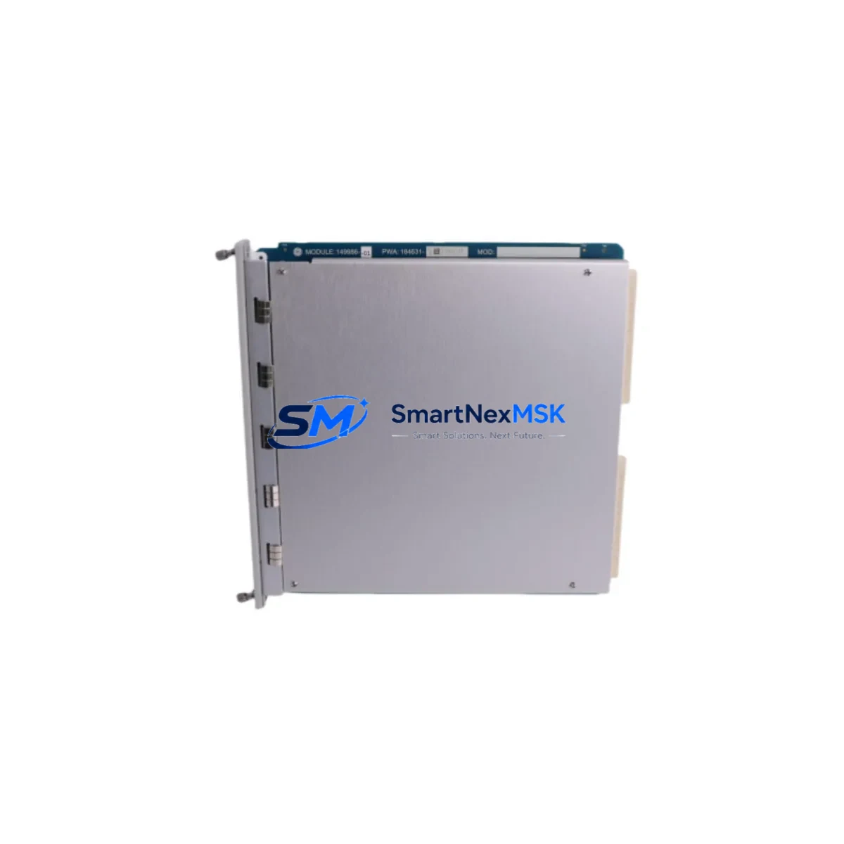
The Bently Nevada 3500/33-149986-01 is a 4-channel Relay Output Module engineered for the Bently Nevada 3500 Series Machinery Protection System (MPS). As a critical output interface within the 3500 rack architecture, this module converts monitor trip signals into relay contact closures that drive external alarms, shutdowns, and annunciator panels in rotating machinery protection applications — including turbines, compressors, pumps, and generators across oil & gas, power generation, and petrochemical facilities.
Sourced as an original spare, the 3500/33-149986-01 is fully compatible with the 3500 Series backplane and rack infrastructure. Each unit undergoes functional verification prior to dispatch, ensuring relay contact integrity, coil resistance, and output logic are within OEM specification. With a 12-month warranty and documented test records available on request, this module supports both emergency replacement and planned maintenance inventory strategies.
Spare Maintenance Table
| Parameter | Specification |
|---|---|
| Part Number | 3500/33-149986-01 |
| Brand | Bently Nevada |
| Series | 3500 Machinery Protection System |
| Module Type | 4-Channel Relay Output Module |
| Output Channels | 4 independent relay outputs |
| Contact Rating | 5A @ 250VAC / 30VDC (per OEM class) |
| Relay Type | Form C (SPDT) relay contacts |
| Rack Compatibility | Bently Nevada 3500 Series rack (standard and TMR) |
| Backplane Interface | 3500 Series internal bus |
| Operating Temperature | 0°C to 65°C (32°F to 149°F) |
| Power Supply | Supplied via 3500/15 or 3500/15E Power Supply Module |
| Weight | 760 g (approx.) |
| Origin | USA |
| Condition | Original spare — tested before shipment |
| Warranty | 12 months from date of shipment |
| Application | Turbines, compressors, pumps, generators — MPS trip/alarm output |
| Maintenance Recommendation | Inspect relay contacts and wiring annually; replace if contact resistance exceeds threshold |
Maintenance Planning for Continuous Operation
When a maintenance or reliability engineer identifies a fault or degradation in the 3500/33-149986-01 Relay Output Module, the replacement workflow rarely ends with the module itself. The 3500 Series rack is an integrated system, and a thorough site inspection should encompass all components that interact with the relay output circuit and the broader MPS architecture.
Begin with the 3500/15 or 3500/15E Power Supply Module, which provides regulated DC power to all modules in the rack. A failing or marginal power supply can cause intermittent relay chatter, false trips, or module resets — symptoms that are often misattributed to the relay output module itself. Verify output voltage rails and ripple before condemning the 3500/33.
Next, inspect the 3500/20 or 3500/20E Rack Interface Module (RIM), which manages communication between the rack and the host DCS or SCADA system via Modbus, Ethernet, or other protocols. If the RIM is logging communication faults coincident with relay anomalies, the root cause may be upstream of the relay output stage. Similarly, review the 3500/22M Transient Data Interface (TDI) if the site uses waveform capture for diagnostics.
For the relay output wiring itself, inspect the 3500/33 I/O module terminal block and field wiring harness. Loose terminations, corroded contacts, or undersized conductors in the external relay circuit can cause contact bounce or failure to energize downstream loads. Verify that external fusing — typically 2A or 5A fast-blow fuses on each relay output leg — is intact and correctly rated. Blown fuses on relay output circuits are a common finding during post-trip inspections.
If the 3500/33 drives annunciator panels or safety relay modules such as a Phoenix Contact or Pilz safety relay, inspect those downstream devices for contact wear or coil degradation. In TMR (Triple Modular Redundant) rack configurations, also verify the 3500/32 4-Channel Relay Output Module (TMR) voting logic and confirm that all three relay channels are responding consistently.
For sites using vibration monitoring inputs, cross-reference the condition of 3500/40M, 3500/42M, or 3500/45 monitor modules that feed trip signals to the relay output module. A monitor module with a degraded channel may generate spurious trip outputs that stress relay contacts over time. Replacing the relay output module without addressing a faulty monitor module upstream will result in premature failure of the new spare.
Finally, review the 3500 rack backplane and chassis for signs of corrosion, contamination, or mechanical damage to the card-edge connectors. In high-humidity or coastal environments, backplane connector oxidation is a known failure mode that affects multiple modules simultaneously. A proactive inspection of the full rack during a planned outage — including the 3500/01 Rack Configuration Module and any installed 3500/92 or 3500/94 communication gateway modules — will reduce the risk of repeat failures and unplanned downtime.
Site Replacement Workflow
Replacing the 3500/33-149986-01 in a live or recently tripped MPS rack follows a structured sequence to minimize downtime and ensure system integrity is restored before returning the machine to service.
Step 1 — Verify the replacement part number. Confirm that the spare on hand matches the exact suffix -149986-01. Bently Nevada uses suffix codes to denote hardware revisions and option configurations; installing an incompatible suffix may result in rack configuration errors or reduced relay contact ratings.
Step 2 — Isolate the relay output circuit. Before removing the module, de-energize the external relay loads connected to the 3500/33 output terminals. This prevents arc damage to the relay contacts during extraction and protects downstream equipment from uncontrolled state changes.
Step 3 — Remove and inspect the failed module. Extract the module from the rack slot and inspect the card-edge connector, relay contact surfaces (if accessible), and PCB for signs of overheating, contamination, or mechanical damage. Document findings for the maintenance record.
Step 4 — Install the replacement 3500/33-149986-01. Seat the module firmly into the rack slot and verify the front-panel LED indicators illuminate correctly upon power-up. The 3500 rack should automatically recognize the module and restore its configuration from the Rack Configuration Module (RCM).
Step 5 — Functional verification. Using the Bently Nevada System 1 software or a portable rack configuration tool, perform a relay output test to confirm each of the 4 channels energizes and de-energizes correctly. Verify that downstream annunciators, shutdown relays, and DCS inputs respond as expected.
Step 6 — Return to service and update maintenance records. Document the replacement date, part number, and test results in the site CMMS. Update the spare parts inventory to trigger reorder of a replacement spare, maintaining minimum stock levels for critical MPS components.
Spare Parts Support FAQ
Q1: Is the 3500/33-149986-01 compatible with both standard and TMR 3500 racks?
The 3500/33-149986-01 is designed for standard (non-TMR) 3500 Series rack configurations. TMR applications typically use the 3500/32 Relay Output Module, which incorporates voting logic for triple-redundant trip circuits. Always verify your rack configuration and slot assignment before ordering. If you are unsure, provide your rack serial number and we can confirm compatibility prior to shipment.
Q2: What testing is performed before shipment?
Each 3500/33-149986-01 unit is functionally tested prior to dispatch. Testing includes relay coil energization, contact continuity verification across all 4 channels, and visual inspection of the PCB and card-edge connector. Test records are available on request. Units are shipped in anti-static packaging with protective end caps to prevent connector damage in transit.
Q3: How should I manage spare parts inventory for the 3500 Series MPS?
For critical rotating machinery protection systems, industry best practice recommends maintaining a minimum of one spare relay output module per rack, with additional spares proportional to the number of racks on site. Given the long lead times historically associated with Bently Nevada OEM channels, sourcing original spares from specialist distributors ensures availability for both planned maintenance and emergency replacement scenarios. A 12-month warranty provides coverage through at least one annual inspection cycle.
Q4: Can the 3500/33-149986-01 replace older or discontinued relay output module variants?
In many cases, yes — provided the hardware suffix and rack slot configuration are compatible. Bently Nevada has periodically revised relay output module part numbers as part of product lifecycle updates. Our technical team can assist with cross-referencing legacy part numbers to confirm whether the 3500/33-149986-01 is a valid replacement for your specific application. Contact us with your existing part number and rack configuration details for a compatibility assessment before ordering.
© 2026 SMARTNEXMSK. All rights reserved.
Original Source: https://smartnexmsk.com
Contact: sales@smartnexmsk.com | +86 18259474341


