Bently Nevada 3500/33 Retrofit-Ready Relay Output Module for 3500 Series Control Systems
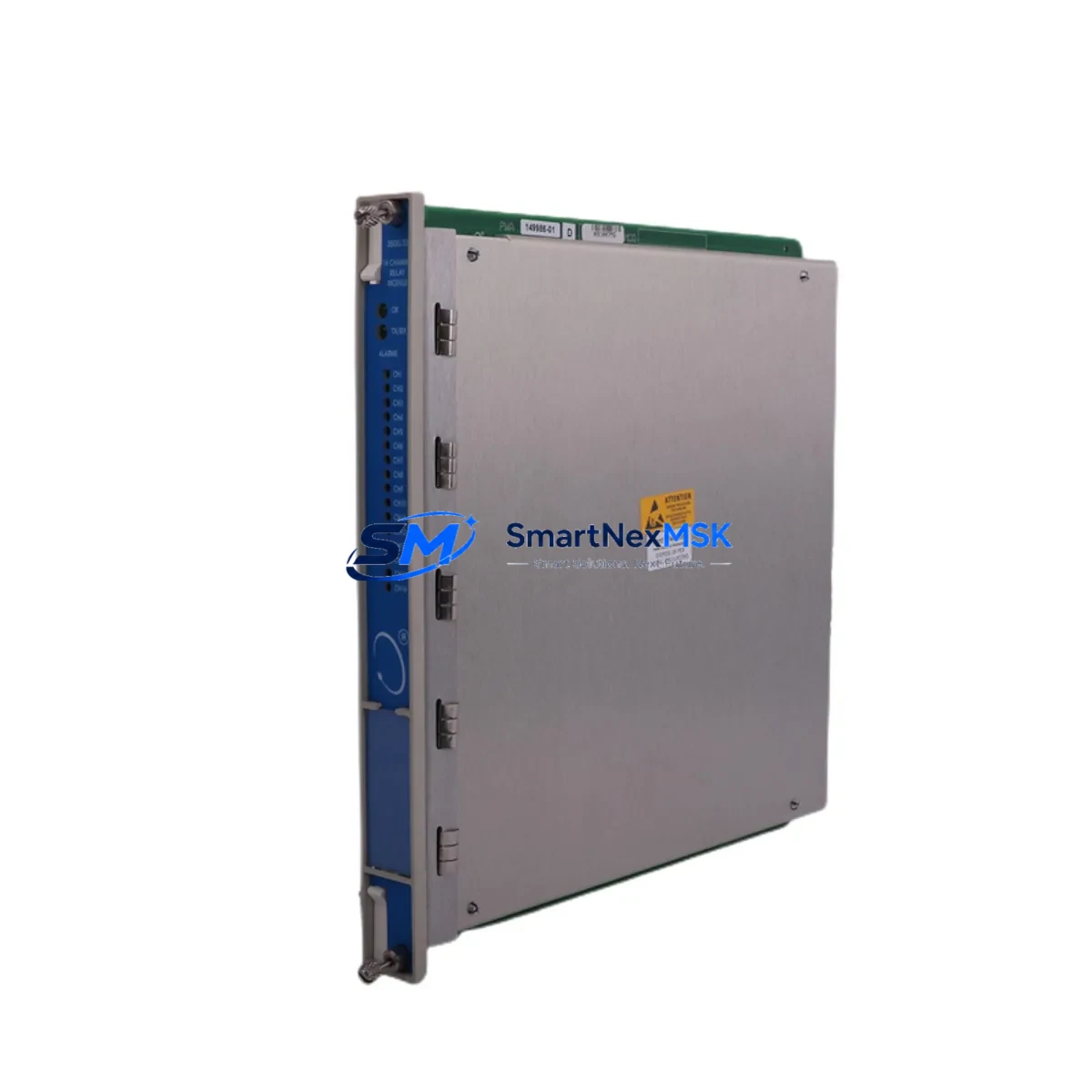
The Bently Nevada 3500/33 is a 16-channel relay output module engineered for the Bently Nevada 3500 Series machinery protection platform. As legacy 3500 Series installations age and original spare parts become increasingly scarce, the 3500/33 has become one of the most sought-after retrofit components for facilities managing turbines, compressors, pumps, and rotating machinery across oil & gas, power generation, and petrochemical industries. This listing provides a verified-compatible, test-passed replacement unit backed by a 12-month warranty and ready for immediate integration into existing 3500 rack assemblies.
Upgrade Compatibility Table
| Parameter | Details |
|---|---|
| Compatible Platform | Bently Nevada 3500 Series Machinery Protection System |
| Module Type | 16-Channel Relay Output Module |
| Rack Interface | 3500 Series backplane — direct plug-in, no adapter required |
| Slot Compatibility | Any relay output slot in 3500/05 or 3500/05E rack chassis |
| Communication | Internal backplane bus; compatible with 3500/22M Transient Data Interface and 3500/92 Communication Gateway |
| Power Requirement | Supplied via 3500 rack power module (3500/15 or 3500/15E); no external power wiring required |
| Terminal Wiring | Standard 3500 Series I/O terminal block; existing field wiring reusable without modification |
| Replacement Scope | Direct drop-in for original 3500/33 units; no firmware re-flash required in most configurations |
| Commissioning | Module address auto-detected by rack; verify relay setpoints via System 1 or Rack Configuration Software |
| Warranty | 12 months from date of shipment; covers manufacturing defects and functional failure |
Retrofit Planning for Existing Automation Systems
Replacing a 3500/33 Relay Output Module within a live 3500 Series rack requires careful pre-outage planning to protect both personnel and process continuity. Before scheduling the swap, engineers should audit the full rack assembly — typically comprising a 3500/05 Rack and Power Supply, one or more 3500/15 Power Supply Modules, monitor modules such as the 3500/40M Proximitor/Seismic Monitor or 3500/42M Proximitor/Seismic Monitor, and a 3500/22M Transient Data Interface for waveform capture. Each of these modules shares the backplane bus, and any relay output reconfiguration can affect alarm and trip logic across the entire rack.
Terminal block wiring on the 3500/33 follows the standard 3500 Series I/O convention. Field cables connected to the existing relay output terminal block can typically be reused without re-termination, provided the cable condition is acceptable. Engineers should photograph or document all terminal assignments before removal. If the installation uses a 3500/92 Communication Gateway for Modbus or OPC connectivity to a DCS or SCADA host, verify that the relay channel mapping in the gateway configuration matches the replacement module’s slot address.
For facilities running System 1 Evolution condition monitoring software, the module replacement is transparent at the software level once the rack re-initializes — relay setpoints, time delays, and latching configurations are stored in the rack’s non-volatile memory and are preserved across module swaps. However, it is best practice to export a full rack configuration backup using the Rack Configuration Software (RCS) before any hardware change. If the site also operates a 3500/20 Rack Interface Module for Ethernet connectivity, confirm that the module’s IP settings and alarm routing tables remain intact post-swap.
In multi-rack installations — common in large turbine trains where a 3500/05E Enhanced Rack may be paired with a standard 3500/05 — relay output modules across both racks should be audited simultaneously. Replacing only the failed 3500/33 without checking adjacent modules for wear or marginal contact resistance can lead to repeat failures within months. Stocking a spare 3500/33 alongside a spare 3500/15 Power Supply Module is a widely adopted best practice in facilities with zero-tolerance for unplanned shutdowns.
Downtime Control During System Migration
Minimizing downtime during a 3500/33 relay output module replacement begins with pre-staging the replacement unit and verifying its functional test report before the maintenance window opens. Our units ship with a completed factory acceptance test (FAT) record, confirming relay contact continuity, coil actuation voltage, and channel isolation. This eliminates on-site incoming inspection time and allows technicians to proceed directly to installation.
The physical swap on a 3500 Series rack is straightforward: the module is secured by a single front-panel locking lever and connects via the backplane edge connector. With the rack powered and other modules remaining in service, the 3500/33 can be hot-swapped in racks that support live insertion — consult your site’s safety procedures and the rack’s power-down requirements before proceeding. Once the replacement module is seated, the rack controller performs an automatic self-test and re-establishes relay output states based on the stored configuration. Relay setpoints, deadbands, and time-delay settings do not need to be re-entered.
To protect original program logic and HMI displays during the migration, no changes to the upstream DCS, PLC, or SCADA configuration are required — the 3500/33 replacement is transparent to the control system host. Alarm and trip relay contacts resume their prior state within seconds of module initialization. Field technicians should confirm relay output status via the front-panel LED indicators and perform a functional trip test on at least one channel before returning the machine train to service. Total replacement time for a prepared team is typically under 30 minutes, keeping unplanned downtime well within acceptable limits for most maintenance contracts.
Retrofit Support FAQ
Q1: Is this 3500/33 unit a direct replacement for my existing module without any configuration changes?
In the vast majority of 3500 Series installations, yes. The 3500/33 replacement seats directly into the same backplane slot, and the rack controller reads the module’s identity automatically. Relay setpoints and channel assignments stored in rack non-volatile memory are applied immediately. The only exception is if the original module carried a custom firmware revision tied to a specific System 1 software version — in that case, confirm the firmware revision number before ordering.
Q2: Can I reuse the existing field wiring and terminal block?
Yes. The 3500/33 uses the standard 3500 Series I/O terminal block format. Existing field cables connected to relay output contacts can be left in place during the module swap. Simply disconnect the terminal block from the old module, seat the replacement, and reconnect. No re-termination or cable labeling changes are required.
Q3: What commissioning steps are required after installation?
After seating the module, verify the front-panel status LEDs indicate normal operation. Use Rack Configuration Software or System 1 to confirm all 16 relay channels are recognized and that setpoint values match the pre-swap backup. Perform a functional trip test on at least one relay channel to confirm contact closure and field device response. Document the test results and update the site maintenance log.
Q4: What does the 12-month warranty cover, and what is the return process?
The 12-month warranty covers all manufacturing defects and functional failures under normal operating conditions within the 3500 Series rack environment. If a unit fails within the warranty period, contact our sales team with the order number and a brief fault description. We will arrange priority replacement shipment and, where required, a root-cause analysis report. Warranty claims are processed within 3 business days of fault confirmation.
© 2026 SMARTNEXMSK. All rights reserved.
Original Source: https://smartnexmsk.com
Contact: sales@smartnexmsk.com | +86 18259474341


