Bently Nevada 3500/40M 140734-01 Maintenance-Ready Spare for 3500 Series Automation
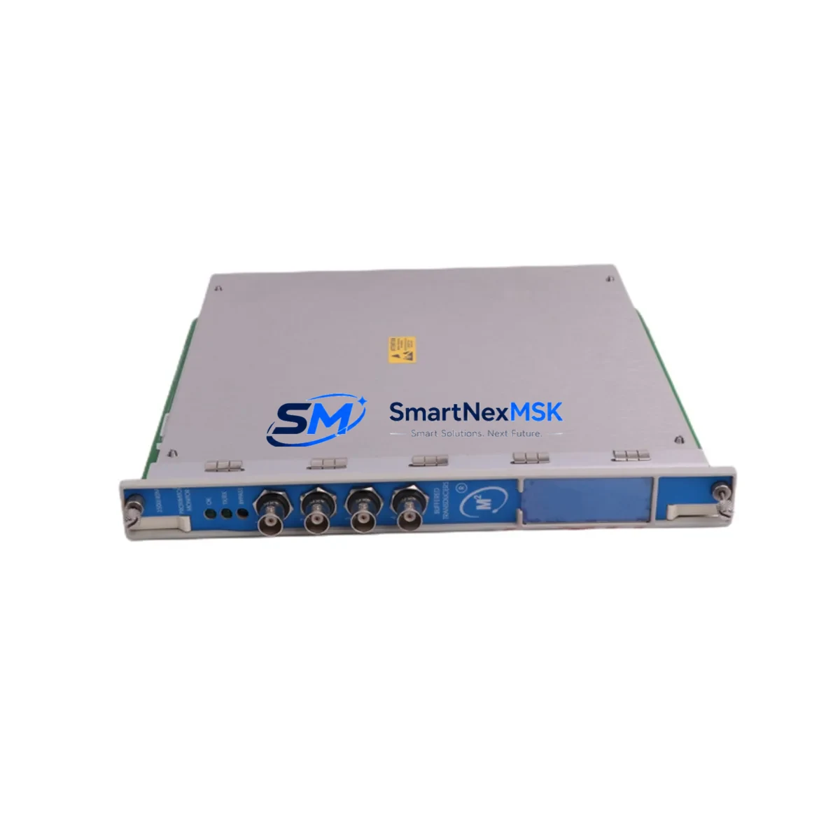
The Bently Nevada 3500/40M 140734-01 is a dual-channel Proximitor/Velomitor monitor module designed for continuous machinery protection within the 3500 Series modular monitoring system. As rotating equipment ages and OEM support windows narrow, maintaining a verified, tested spare of the 3500/40M 140734-01 in your critical spare parts inventory is one of the most effective strategies for reducing unplanned downtime and protecting high-value rotating assets such as compressors, turbines, pumps, and fans.
This module accepts inputs from proximity probes and Velomitor sensors, providing real-time radial vibration and velocity measurements. It integrates directly into the 3500 Series rack architecture, communicating with the 3500/01 Rack Interface Module and the 3500/05 System Display and Reset Module. For maintenance engineers managing aging machinery protection systems, having a pre-tested 3500/40M 140734-01 on the shelf means the difference between a two-hour swap and a multi-day outage waiting for emergency procurement.
From a procurement engineering perspective, the 3500/40M 140734-01 is a long-lifecycle module that remains widely deployed across petrochemical, power generation, and heavy manufacturing facilities. SMARTNEXMSK supplies this module as an original spare, fully tested prior to shipment, with a 12-month warranty covering functional performance under normal operating conditions.
Spare Maintenance Table
| Part Number | 3500/40M 140734-01 |
| Brand | Bently Nevada |
| Series | 3500 Series Modular Monitoring System |
| Module Type | Dual-Channel Proximitor / Velomitor Monitor |
| Input Channels | 2 (Radial Vibration / Velocity) |
| Sensor Compatibility | Proximitor sensors (eddy-current), Velomitor velocity sensors |
| Rack Compatibility | Bently Nevada 3500 Series rack (3500/01 RIM required) |
| Communication | Rack backplane; compatible with 3500 Series Ethernet/Serial gateway modules |
| Application Environment | Rotating machinery protection: compressors, turbines, pumps, fans |
| Operating Temperature | 0°C to 65°C (standard industrial enclosure) |
| Installation | Plug-in module, 3500 Series rack slot |
| Origin | United States |
| Condition | Original spare, pre-shipment functional test |
| Warranty | 12 Months |
| Lead Time | In stock — ships within 3 business days |
Maintenance Planning for Continuous Operation
When scheduling a planned inspection or responding to a vibration alarm on a 3500 Series rack, the 3500/40M 140734-01 is rarely the only component that warrants attention. A thorough maintenance review of the control cabinet and sensor loop should include the following associated components:
Begin with the 3500/01 Rack Interface Module, which governs all backplane communications — a degraded RIM can produce false alarms or mask genuine vibration events. Verify the 3500/05 System Display and Reset Module for alarm acknowledgment integrity. Inspect the 3500/15 Power Supply Module (or 3500/15E enhanced version) for output voltage stability, as power fluctuations are a leading cause of spurious trips in vibration monitoring systems.
On the sensor side, check the Bently Nevada 3300 XL 8mm Proximity Probe and its associated 3300 XL Extension Cable for continuity, insulation resistance, and connector condition. Proximitor driver gap voltage should be verified at the field junction box before condemning the monitor module. If Velomitor sensors are in use, inspect the Velomitor SP sensor cable terminations and confirm the sensor body is free of mechanical damage or moisture ingress.
For facilities running hybrid protection architectures, also review the 3500/22M Transient Data Interface if transient capture is enabled, and confirm that the 3500/92 Communication Gateway Module (Modbus or Ethernet) is correctly mapped to the SCADA or DCS historian. Fuse holders and terminal blocks within the marshalling cabinet should be inspected for corrosion, especially in humid or coastal environments. Maintaining a documented spare parts list that includes the 3500/40M 140734-01 alongside these associated modules ensures that your maintenance team can execute a full rack restoration without secondary procurement delays.
Site Replacement Workflow
Replacing the 3500/40M 140734-01 in the field is a structured process that, when executed correctly, minimizes rack downtime to under two hours for experienced technicians:
1. Pre-Replacement Verification: Confirm the replacement module’s part number and revision suffix match the installed unit. The 140734-01 revision suffix is critical — do not substitute with alternate revisions without consulting the 3500 Series configuration documentation. Record current alarm setpoints and channel configuration from the 3500 Configuration Software before removal.
2. Safe Isolation: Notify the control room and place the affected channels in bypass mode via the 3500/05 System Display or the configuration software. This prevents spurious trips during the swap. De-energize the rack slot if hot-swap is not confirmed for your firmware revision.
3. Module Extraction and Installation: Remove the existing 3500/40M module by releasing the front-panel locking screws and sliding the module from the rack. Insert the replacement 3500/40M 140734-01, ensuring full backplane connector engagement. Restore power and verify the module self-test LED sequence.
4. Configuration Restore: Re-apply the saved channel configuration using the 3500 Configuration Software. Verify gap voltage, OK limits, and alarm setpoints for both channels. Confirm the module appears correctly in the rack inventory display on the 3500/05.
5. Return to Service: Remove bypass mode, confirm live vibration readings are within expected baseline range, and document the replacement in the equipment maintenance log. Retain the removed module for bench evaluation before disposal or return.
This workflow is compatible with both legacy 3500 racks and updated rack configurations running current firmware, ensuring system continuity without requiring a full rack reconfiguration.
Spare Parts Support FAQ
Q1: What is the expected service life of the 3500/40M 140734-01, and when should I plan for replacement?
The 3500/40M 140734-01 is a mature, long-lifecycle module. In stable environments, units routinely operate for 10–15 years. Replacement is typically triggered by calibration drift, intermittent OK relay faults, or backplane connector wear. Proactive replacement during scheduled turnarounds — rather than waiting for failure — is the recommended strategy for critical machinery protection loops.
Q2: How do I verify compatibility before ordering a replacement module?
Confirm the rack model (3500 Series), the existing module part number (3500/40M), and the revision suffix (140734-01) from the module faceplate or the rack configuration report. SMARTNEXMSK can provide compatibility confirmation based on your rack serial number and firmware version upon request before order placement.
Q3: What pre-shipment testing is performed on this module?
Each 3500/40M 140734-01 supplied by SMARTNEXMSK undergoes functional verification prior to shipment, including power-on self-test confirmation, channel input response check, and OK relay output verification. Modules are shipped in anti-static packaging with a test record. The 12-month warranty covers functional failure under normal operating conditions from the date of receipt.
Q4: Can SMARTNEXMSK support long-term or blanket spare parts orders for the 3500 Series?
Yes. For facilities managing multiple 3500 Series racks or planning multi-year maintenance contracts, SMARTNEXMSK offers long-term supply agreements for the 3500/40M 140734-01 and associated 3500 Series modules. Contact our team to discuss inventory reservation, lead time commitments, and volume pricing for your spare parts program.
© 2026 SMARTNEXMSK. All rights reserved.
Original Source: https://smartnexmsk.com
Contact: sales@smartnexmsk.com | +86 18259474341


