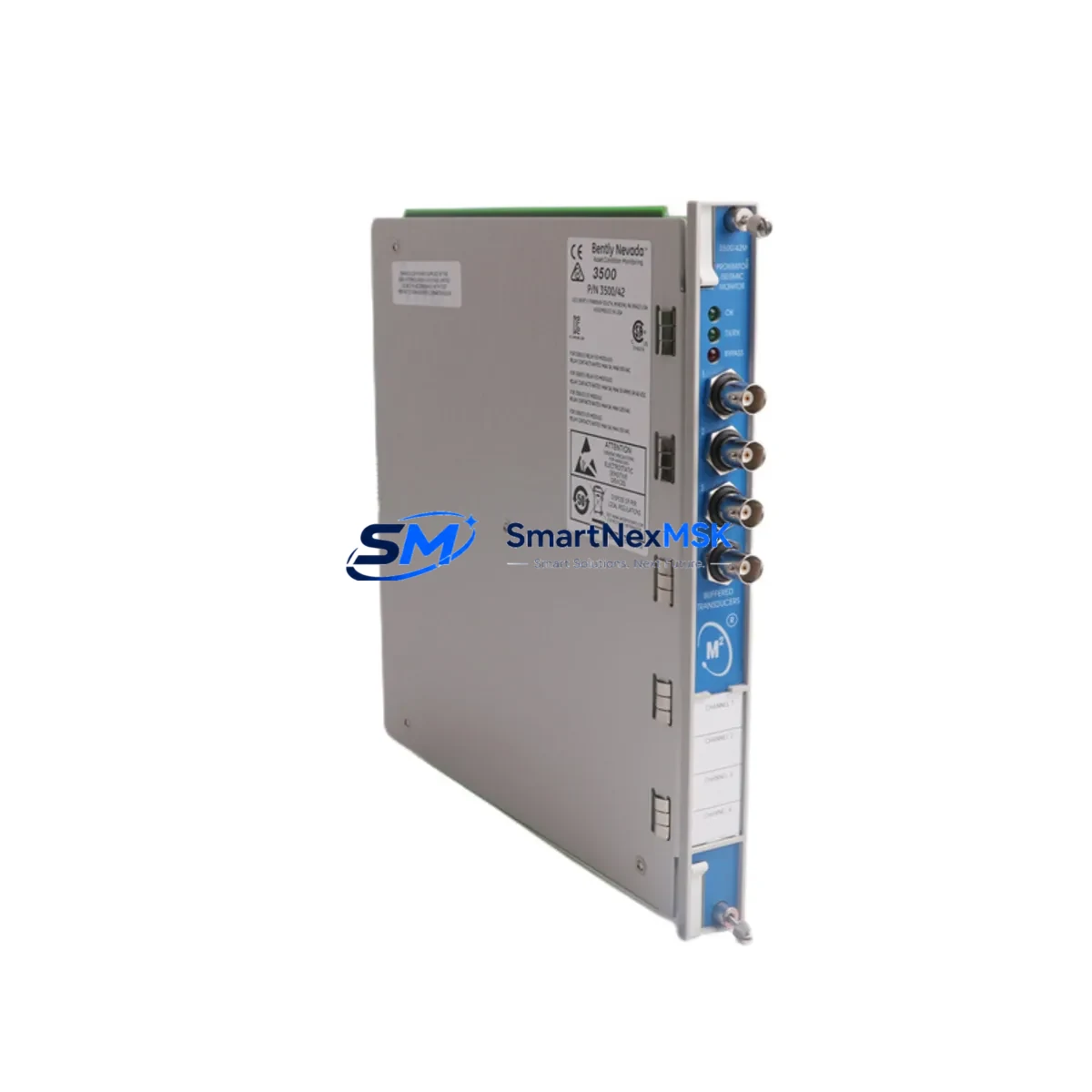
Bently Nevada 3500/42 176449-02 Retrofit Vibration Monitor for 3500 Series Control Systems
The Bently Nevada 3500/42 176449-02 is a dual-channel vibration monitor designed for continuous machinery protection within the 3500 Series modular monitoring rack. As legacy installations age and OEM support for older 3500/40M and 3500/42M configurations is phased out, the 3500/42 176449-02 has become the preferred retrofit-ready replacement for facilities seeking to modernize their rotating equipment protection systems without a full platform migration. Whether you are upgrading a turbine control cabinet, replacing a failed card in a compressor protection rack, or migrating from an earlier 3500 Series revision, this module delivers the measurement accuracy and system compatibility your operation demands.
Upgrade Compatibility Table
| Parameter | Details |
|---|---|
| Replaces / Upgrades | 3500/40M, 3500/42M, 3500/42 176449-01 and earlier revisions |
| Rack Compatibility | 3500 Series 19-inch rack (3500/05, 3500/15, 3500/20 power supplies supported) |
| Backplane Interface | Standard 3500 Series backplane — no adapter required for direct slot replacement |
| Communication Protocol | RS-232 / RS-485 Modbus RTU; compatible with 3500/92 Communication Gateway |
| Transducer Input | Compatible with 3300 XL 8mm and 11mm proximity probe systems, including 330101 and 330180 series |
| Keyphasor Input | Accepts Keyphasor signal from 3500/17 Keyphasor module — no rewiring required |
| Installation Requirement | Slot-in replacement; verify rack power budget with 3500/15 or 3500/20 power supply |
| Configuration Tool | Rack Configuration Software (RCS) v3.x or later; existing .rck files are forward-compatible |
| Commissioning Focus | Verify channel OK relay, alert/danger setpoints, and Modbus register mapping after swap |
| Warranty | 12-Month Warranty — covers manufacturing defects and functional performance |
Retrofit Planning for Existing Automation Systems
Successful integration of the 3500/42 176449-02 into an existing machinery protection system begins well before the module arrives on site. Engineers should start by auditing the current rack configuration using the 3500 Rack Configuration Software to export the active .rck file. This file documents every channel assignment, setpoint, relay logic, and Modbus address currently in service — preserving it is the single most important step before any hardware swap.
In most 3500 Series installations, the vibration monitor shares a rack with the 3500/17 Keyphasor module, which provides the once-per-revolution reference signal for phase and speed measurements. Confirm that the Keyphasor wiring to terminal block TB1 remains undisturbed during the card swap. Similarly, the 3500/20 rack power supply or 3500/15 power supply should be checked for available current headroom — the 3500/42 176449-02 draws approximately 350 mA at 24 VDC, and a rack already loaded with I/O modules, the 3500/92 communication gateway, and a 3500/32 four-channel relay module may be operating near its power budget limit.
Transducer wiring from the 330101-00-15-10-02-00 proximity probe or the 330180-51-05 extension cable connects to the monitor’s front-panel terminal block. Verify that the driver/extension cable combination has not exceeded the recommended total cable length for the 3300 XL system — typically 9 meters for the standard configuration. If the existing installation uses a 3300/16 proximitor sensor, confirm the output voltage range is within the 3500/42 input specification before powering up.
For facilities running DCS integration through a 3500/92 Ethernet communication module, the Modbus TCP register map should be validated against the SCADA or DCS tag database. In Honeywell Experion or Emerson DeltaV environments, this typically means updating the I/O server configuration to reflect any register offset changes introduced by the new module revision. HMI faceplate displays tied to vibration trend tags should be tested in simulation mode before returning the machine to service.
Where the control cabinet also houses a 3500/61 temperature monitor or a 3500/64 dynamic pressure monitor, the relay output wiring from the 3500/32 relay module should be traced and documented. Relay assignments for alert and danger conditions are stored in the .rck configuration file, but physical wiring to the trip solenoid or DCS digital input card must be verified independently. A pre-swap loop check using a milliamp source on each relay output is strongly recommended.
Downtime Control During System Migration
Minimizing unplanned downtime during a 3500/42 176449-02 swap requires a structured hot-swap protocol. Because the 3500 Series rack does not support live card removal under power in most configurations, the preferred approach is a planned maintenance window coordinated with the operations team. Before de-energizing the rack, export the current .rck configuration file and store it on a laptop running the Rack Configuration Software. This ensures that if the replacement module requires re-configuration, the original setpoints, channel assignments, and relay logic can be restored in minutes rather than hours.
During the swap window, the machine should be placed in a controlled shutdown state with the trip system bypassed through the 3500/32 relay module’s bypass input — never by physically disconnecting relay wiring. Once the new 3500/42 176449-02 is seated and the rack is re-energized, the RCS software will detect the new module and prompt for configuration download. Load the saved .rck file, verify the channel OK status on each channel, and confirm that the Keyphasor signal from the 3500/17 module is being received correctly before releasing the bypass.
For critical machinery where even a brief monitoring gap is unacceptable, a portable vibration analyzer connected to the proximity probe junction box can maintain continuous trend logging throughout the swap procedure. This approach is particularly valuable in compressor trains where the 3300 XL probe system feeds both the protection rack and a condition monitoring system simultaneously. Once the 3500/42 176449-02 is confirmed operational and all Modbus tags are verified live in the DCS, the portable analyzer can be disconnected and the machine returned to normal operation.
Retrofit Support FAQ
Q: Is the 3500/42 176449-02 a direct drop-in replacement for the 176449-01 revision?
A: Yes. The 176449-02 is backward-compatible with the 176449-01 at the rack backplane and terminal block level. No wiring changes are required. The existing .rck configuration file is forward-compatible, though we recommend downloading and verifying the configuration after installation to confirm all setpoints transferred correctly.
Q: What commissioning steps are required after installing the replacement module?
A: After seating the module and powering the rack, connect a laptop running the 3500 Rack Configuration Software and download the saved .rck file. Verify channel OK status, confirm alert and danger setpoint values, check Keyphasor signal reception from the 3500/17 module, and validate Modbus register responses from the 3500/92 gateway. Perform a relay output loop check on the 3500/32 relay module before releasing the machine to service.
Q: Does the module ship pre-tested?
A: Yes. Every 3500/42 176449-02 unit undergoes functional testing prior to shipment, including channel response verification, relay output confirmation, and communication interface check. A test report is available upon request. The module is covered by a 12-month warranty from the date of shipment, covering manufacturing defects and functional performance under normal operating conditions.
Q: What if my existing proximity probe wiring is not compatible with the new module’s terminal block?
A: The 3500/42 176449-02 uses the same front-panel terminal block pinout as previous 3500/42 revisions. If your installation uses a 3300 XL 8mm or 11mm probe with a standard Bently Nevada extension cable, no wiring changes are required. For non-standard installations or third-party probe systems, contact our technical team to confirm compatibility before ordering.
© 2026 SMARTNEXMSK. All rights reserved.
Original Source: https://smartnexmsk.com
Contact: sales@smartnexmsk.com | +86 18259474341


