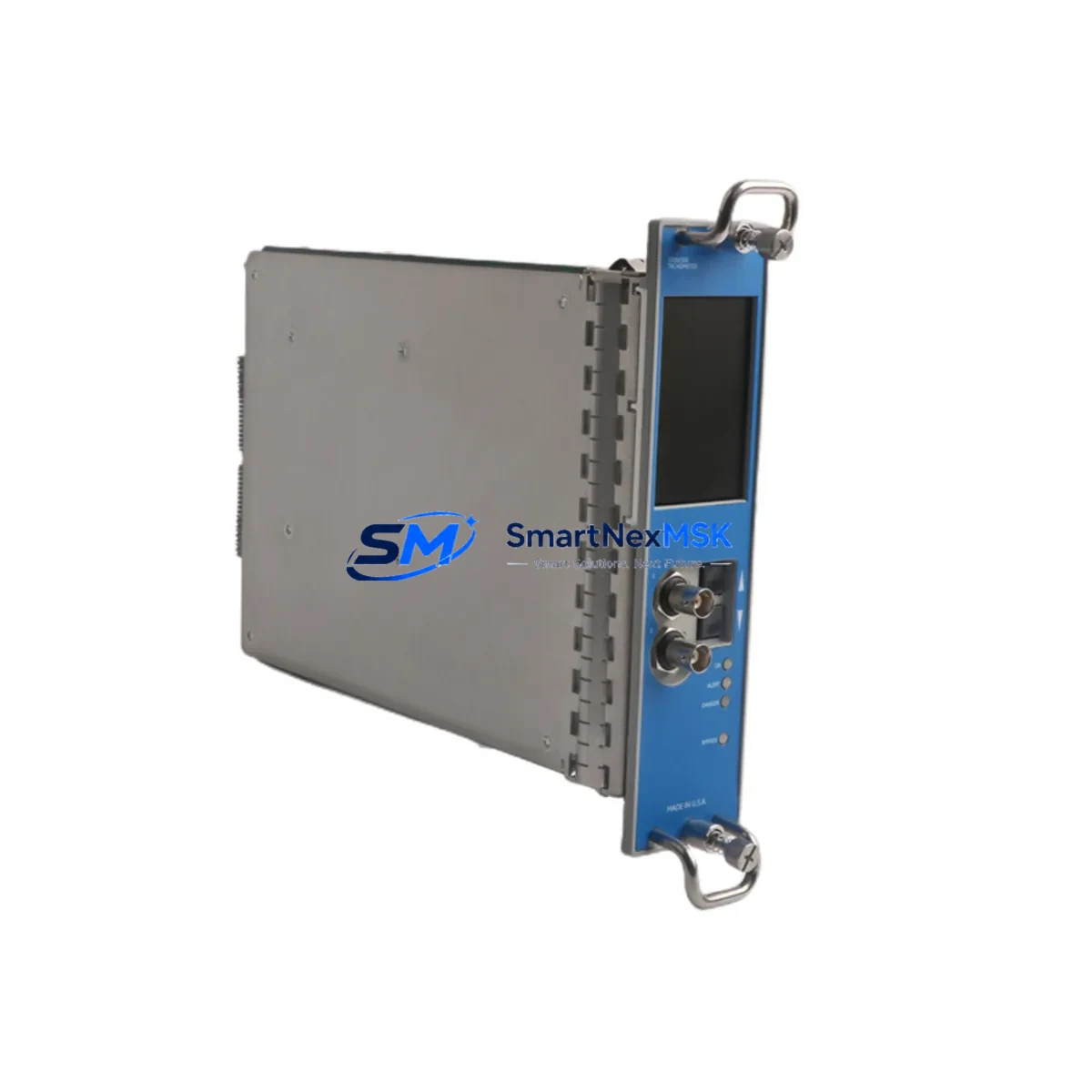
Bently Nevada 3500/50E Retrofit-Ready Speed Monitor for 3500 Series Control Systems
The Bently Nevada 3500/50E is a dual-channel tachometer and overspeed detection module engineered for seamless integration into the 3500 Series machinery protection framework. As legacy speed monitoring hardware reaches end-of-life across refineries, power generation facilities, compressor stations, and rotating equipment platforms, the 3500/50E stands as the authoritative retrofit solution — delivering drop-in mechanical compatibility, full firmware continuity, and validated signal integrity without requiring rack redesign or software re-engineering.
For maintenance engineers managing aging turbine protection systems, the 3500/50E addresses the most critical challenge in brownfield upgrades: replacing a discontinued or degraded speed monitor without triggering a cascade of downstream configuration changes. The module slots directly into the 3500 Series rack backplane, preserving existing terminal wiring, channel addressing, and communication links to the host system. Engineers can validate the replacement against the original 3500 Rack Configuration Software (RCS) database without rebuilding logic trees or recalibrating trip setpoints.
Each unit shipped by SMARTNEXMSK undergoes pre-delivery functional verification, including channel-to-channel isolation testing, keyphasor signal simulation, and overspeed trip threshold confirmation. Units are supplied with a 12-month warranty covering manufacturing defects and functional performance, with documented test records available upon request.
Upgrade Compatibility Table
| Parameter | Detail |
|---|---|
| Compatible Rack | Bently Nevada 3500 Series (standard 19″ rack) |
| Backplane Interface | 3500 Series standard backplane connector — no adapter required |
| Channel Configuration | Dual-channel tachometer / overspeed detection |
| Input Signal | Magnetic pickup (MPU) or proximity probe (eddy-current) |
| Communication | 3500 Series internal rack bus; compatible with 3500/22M Communication Gateway |
| Configuration Tool | Bently Nevada Rack Configuration Software (RCS) |
| Replacement Fit | Drop-in; preserves existing terminal block wiring and slot addressing |
| Firmware Compatibility | Compatible with existing 3500 Series firmware revisions |
| Commissioning Requirement | Channel address verification; trip setpoint confirmation via RCS |
| Warranty | 12 months from shipment date |
Retrofit Planning for Existing Automation Systems
A successful 3500/50E retrofit begins well before the module arrives on-site. The first step is a rack audit: confirm the target slot is a valid speed monitor position within the 3500 Series rack, and verify that the 3500/01 Rack Power Supply is delivering stable ±24 VDC to the backplane. Insufficient power headroom — particularly in racks already populated with I/O-dense modules such as the 3500/40M Proximitor/Seismic Monitor or the 3500/42M Proximitor/Seismic Monitor — can cause intermittent module faults after replacement.
Terminal wiring should be documented before removal of the legacy module. The 3500/50E uses the same I/O terminal block format as predecessor speed monitors in the 3500 family, but engineers should confirm wire labeling against the original loop drawings, particularly for keyphasor inputs shared with the 3500/25 keyphasor module. Shared keyphasor signals feeding multiple protection channels must be re-verified for signal level and frequency range after the new module is seated.
For facilities running Modbus or OPC-DA data highways, the 3500/22M Communication Gateway module should be checked for firmware compatibility with the replacement 3500/50E. In most cases, no gateway reconfiguration is required, but the channel tag mapping in the SCADA historian — whether running on a PI Server, Wonderware InTouch, or FactoryTalk View SE platform — should be validated to confirm that speed and overspeed tags are still resolving correctly after the swap.
Where the control architecture includes a Bently Nevada System 1 condition monitoring platform, the 3500/50E channel data will continue to feed System 1 via the existing rack communication path. Engineers should confirm that the System 1 machine train configuration still references the correct slot and channel numbers after the module replacement, and that alarm thresholds have not been inadvertently reset to factory defaults during the RCS download.
In multi-rack installations — common in large gas turbine or steam turbine protection panels — the 3500/50E replacement should be coordinated with the overall rack sequencing plan. Racks sharing a common 3500/20 Rack Interface Module should be assessed for any cross-rack dependencies before the target module is pulled. Spare 3500 Series I/O modules, including the 3500/15 Power Supply Input Module and any installed 3500/32 4-Channel Relay Module units, should be confirmed as functional before the maintenance window begins to avoid compounding faults during the cutover.
Downtime Control During System Migration
Minimizing unplanned downtime during a 3500/50E replacement requires a structured pre-outage checklist and a clear rollback plan. Before the maintenance window opens, the existing module configuration should be exported from the Rack Configuration Software and archived. This export preserves all channel setpoints, filter settings, full-scale ranges, and trip multiply states — ensuring that if the replacement module requires a fresh RCS download, the original parameters can be restored in minutes rather than hours.
During the physical swap, the rack should remain powered where plant safety procedures permit a hot-swap sequence. The 3500 Series architecture supports module replacement under power in most configurations, allowing adjacent channels to remain in protection service while the target slot is serviced. Engineers should confirm the specific hot-swap authorization for their rack revision and firmware level before proceeding.
After seating the 3500/50E, the commissioning sequence should follow a defined order: first confirm module self-test pass via the front-panel LED indicators, then connect the RCS laptop via the rack’s front-panel communication port, download the archived configuration, and verify channel status before re-enabling trip outputs. Keyphasor signal quality should be confirmed on both channels using the RCS live data view before the unit is returned to normal protection service.
For facilities where continuous protection coverage is mandatory, a temporary bypass relay — such as those available through the 3500/32 relay module — can be configured to hold the last valid trip state during the swap window, preventing nuisance trips while the replacement module initializes. This approach is particularly valuable in combined-cycle power plants and offshore compression platforms where a spurious overspeed trip carries significant production and safety consequences.
Retrofit Support FAQ
Q: Is the 3500/50E a direct drop-in replacement for all speed monitor variants in the 3500 Series rack?
A: The 3500/50E is compatible with standard speed monitor slot positions in the 3500 Series rack. Engineers should confirm the specific slot designation in their rack configuration file, as some legacy installations may use earlier speed monitor variants with different terminal block pinouts. SMARTNEXMSK can provide pre-shipment configuration verification upon request.
Q: Does the replacement module require a new RCS configuration download, or will it inherit the existing rack settings?
A: In most cases, the 3500/50E will require an RCS configuration download to the new module after installation. The existing rack configuration file should be exported before the swap and re-applied after the module is seated. This process typically takes 15–30 minutes and does not require changes to adjacent module configurations.
Q: How should terminal wiring be verified before and after the replacement?
A: All field wiring should be documented against the original loop drawings before the legacy module is removed. After the 3500/50E is installed, each terminal connection should be verified for correct position and torque. Keyphasor and speed sensor signal levels should be confirmed via the RCS live channel display before trip outputs are re-enabled.
Q: What does the 12-month warranty cover, and what documentation is provided with each unit?
A: Each 3500/50E supplied by SMARTNEXMSK carries a 12-month warranty from the shipment date, covering manufacturing defects and functional performance under normal operating conditions. Units are supplied with a functional test record. Extended warranty and on-site commissioning support options are available — contact sales@smartnexmsk.com for details.
© 2026 SMARTNEXMSK. All rights reserved.
Original Source: https://smartnexmsk.com
Contact: sales@smartnexmsk.com | +86 18259474341


