Bently Nevada 3500/61 136711-02 Spare for 3500 Automation: Spare Replacement & Industrial Downtime Risk Control
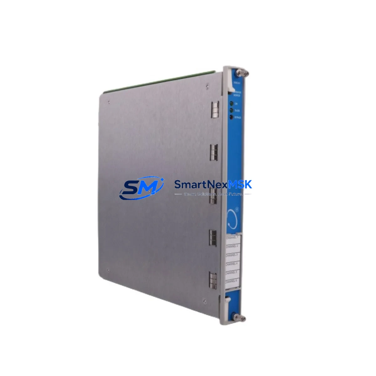
The Bently Nevada 3500/61 136711-02 is an original multi-channel temperature monitor module engineered for the 3500 Series Machinery Protection System — one of the most widely deployed continuous monitoring platforms in rotating equipment protection. Designed for turbines, compressors, pumps, and generators operating in oil & gas, power generation, petrochemical, and heavy industrial environments, this module provides critical temperature measurement and alarm output functions that are central to predictive maintenance strategies and unplanned shutdown prevention.
When a temperature monitor module fails or degrades in a 3500 rack, the consequences extend beyond a single channel. The entire machinery protection loop may be compromised, triggering nuisance trips or — more dangerously — masking real thermal excursions. Maintaining a verified, tested spare of the 3500/61 136711-02 in your site inventory is a fundamental element of any responsible maintenance engineering plan. This unit ships fully tested, with a 12-month warranty, and is ready for immediate rack installation.
Spare Maintenance Table
| Parameter | Specification / Detail |
|---|---|
| Part Number / SKU | 3500/61 136711-02 |
| Brand | Bently Nevada |
| Series | 3500 Machinery Protection System |
| Module Type | Temperature Monitor Module |
| Input Type | Thermocouple / RTD (multi-channel) |
| Rack Compatibility | 3500 Series Rack (3500/20 or 3500/05 rack chassis) |
| Communication | Rack backplane bus; compatible with 3500/92 communication gateway |
| Power Supply | Supplied via 3500 rack backplane (3500/15 power supply module) |
| Origin | USA |
| Condition | Original, surplus new / refurbished-tested |
| Pre-shipment Test | Full functional test performed before dispatch |
| Warranty | 12 Months |
| Shipping | Worldwide express; ESD-safe packaging |
| Application Environment | Industrial control rooms, turbine protection panels, compressor skids |
| Maintenance Recommendation | Inspect terminal wiring, verify rack slot integrity, confirm firmware revision compatibility before installation |
Maintenance Planning for Continuous Operation
Replacing the 3500/61 136711-02 in a live 3500 rack is rarely an isolated task. Maintenance engineers and reliability teams should treat this module swap as an opportunity to audit the surrounding system components to prevent repeat failures and ensure the protection loop is fully restored.
Begin with the 3500/15 power supply module — verify output voltage stability and check for capacitor aging, particularly in racks that have been in service for more than five years. A marginal power supply is a common root cause of intermittent monitor faults that are incorrectly attributed to the monitor module itself.
Inspect all thermocouple and RTD field wiring at the I/O terminal blocks. Corroded or loose connections at the 3500/61 I/O module terminal strip will produce erratic temperature readings even after a module replacement. Use a calibrated signal injector to verify each channel independently before returning the system to service.
Check the 3500/20 rack interface module and backplane connectors for oxidation or mechanical damage. In high-vibration environments, backplane connector integrity is a frequent but overlooked failure point. While the rack is partially powered down for module swap, inspect adjacent slots — particularly any 3500/40M proximitor/seismic monitor or 3500/42M vibration monitor modules sharing the same rack — for alarm LED status and connector seating.
For systems integrated with a DCS or SCADA platform via the 3500/92 communication gateway module, confirm that Modbus or OPC data tags for the replaced channels are re-mapped and validated after installation. A common post-replacement oversight is leaving stale alarm setpoints or incorrect engineering unit scaling in the gateway configuration.
If the 3500 rack feeds alarm outputs to a relay output module (3500/32 or 3500/33), test each relay trip output under simulated alarm conditions before returning the machine to operation. Also verify that any signal isolators or barriers in the thermocouple loop — particularly in hazardous area installations — are within calibration and have not been affected by the fault event that caused the original module failure.
For sites running legacy 3500 racks alongside newer Bently Nevada System 1 software, confirm that the replacement module’s firmware revision is compatible with the installed System 1 version to avoid communication dropouts or unrecognized module errors.
Site Replacement Workflow
Step 1 — Pre-replacement verification: Confirm the failed module’s part number (3500/61 136711-02) against the rack slot label and system documentation. Cross-reference with the machine train’s protection philosophy document to understand which channels are active and what alarm/trip setpoints are configured.
Step 2 — Safe isolation: Coordinate with operations to place the machine in a safe state or bypass mode per site procedures. Do not remove the module under full rack power without confirming bypass status — an unprotected machine trip during module swap can cause more damage than the original fault.
Step 3 — Module extraction and inspection: Remove the 3500/61 136711-02 carefully, inspect the backplane connector pins for damage, and document the slot position. Retain the failed module for failure analysis if required by your maintenance management system.
Step 4 — Spare installation: Insert the replacement 3500/61 136711-02 into the correct rack slot. Confirm the module is fully seated and the front panel locking mechanism is engaged. Reconnect the I/O terminal block and verify wiring integrity.
Step 5 — Commissioning and return to service: Power up the rack, confirm the module is recognized by the rack interface, verify all channel readings against known reference temperatures, and clear any latched alarms. Remove bypass and return the machine to normal protection status. Document the replacement in your CMMS.
This workflow is designed to minimize total downtime from fault detection to return-to-service, typically achievable within a planned maintenance window of 2–4 hours when a tested spare is available on-site.
Spare Parts Support FAQ
Q1: Is the 3500/61 136711-02 a direct drop-in replacement for earlier 3500/61 revisions?
In most cases, yes. The 136711-02 revision is backward compatible with standard 3500 rack configurations. However, if your system is running an older firmware baseline on the rack interface module, verify the revision compatibility matrix in the Bently Nevada 3500 Series installation manual or contact our technical team before installation. We can assist with revision-specific sourcing if required.
Q2: What pre-shipment testing is performed on this module?
Every 3500/61 136711-02 unit we supply undergoes a full functional test prior to dispatch, including channel input verification, alarm output confirmation, and backplane communication check. A test report is available upon request. Units are shipped in ESD-safe packaging with anti-static protection to prevent transit damage.
Q3: How should I manage spare inventory for 3500 Series modules at my site?
Industry best practice for critical rotating equipment protection systems is to maintain at least one verified spare for each module type installed in your 3500 racks. For high-criticality machines (main turbines, primary compressors), consider holding two spares. Rotate spares into service on a scheduled basis and re-test pulled modules to confirm they remain serviceable. Our team can support long-term supply agreements to ensure consistent availability.
Q4: What is covered under the 12-month warranty?
The 12-month warranty covers manufacturing defects and functional failures under normal operating conditions. It does not cover damage resulting from incorrect installation, overvoltage events, or physical mishandling. In the event of a warranty claim, we provide advance replacement to minimize your downtime — you will not be left waiting for a repair cycle before receiving a functional unit.
© 2026 SMARTNEXMSK. All rights reserved.
Original Source: https://smartnexmsk.com
Contact: sales@smartnexmsk.com | +86 18259474341


