Bently Nevada 3500/61E 285694-02 Spare 3500 Series: Maintenance-Ready Replacement for Industrial Downtime Control
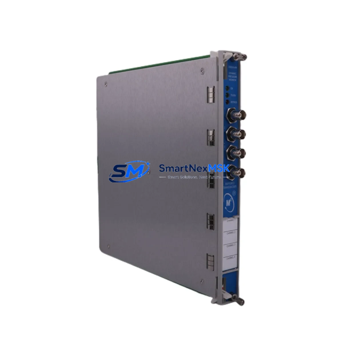
The Bently Nevada 3500/61E 285694-02 is an original dynamic pressure monitor module designed for continuous machinery protection within the 3500 Series monitoring system. In industrial facilities where rotating equipment reliability is non-negotiable — compressors, turbines, pumps, and gearboxes — this module serves as a critical front-line component for detecting dynamic pressure fluctuations, surge events, and process instabilities. Holding a verified spare of the 285694-02 in your maintenance inventory is a proven strategy for minimizing unplanned downtime and accelerating fault recovery when primary units fail or degrade.
Maintenance engineers and reliability teams operating Bently Nevada 3500 Series racks understand that a single failed monitor card can take an entire protection loop offline. The 3500/61E 285694-02 is a hot-swap-compatible module that slots directly into the 3500 rack backplane, restoring full dynamic pressure monitoring capability without requiring system reconfiguration when replaced with an identical part number. This makes it an ideal candidate for critical spare parts lists in petrochemical, power generation, oil & gas, and heavy manufacturing environments.
Spare Maintenance Table
| Parameter | Specification / Detail |
|---|---|
| Part Number / SKU | 285694-02 |
| Module Designation | 3500/61E Dynamic Pressure Monitor |
| Series Compatibility | Bently Nevada 3500 Series Machinery Protection System |
| Rack Interface | 3500 Series backplane (2-slot module) |
| Input Channels | 4 dynamic pressure input channels |
| Signal Input Type | Piezoelectric / dynamic pressure transducer compatible |
| Power Supply | Supplied via 3500 rack backplane (3500/15 or 3500/20 power module) |
| Communication | Rack-level Modbus / System 1 integration via 3500/22M gateway |
| Operating Temperature | 0°C to +60°C (module ambient) |
| Mounting | DIN-rail rack slot, front-panel accessible |
| Origin | USA (Original Bently Nevada manufacture) |
| Condition | Original spare — tested, verified, ready to ship |
| Warranty | 12 Months from date of shipment |
| Typical Application | Compressor surge detection, turbine dynamic pressure monitoring, pump cavitation detection |
| Maintenance Recommendation | Inspect transducer cabling and connector integrity at each planned shutdown; verify channel OK status via System 1 software |
Maintenance Planning for Continuous Operation
When scheduling a replacement of the 3500/61E 285694-02, a thorough maintenance engineer will treat the swap as an opportunity to audit the entire dynamic pressure monitoring loop. Begin by verifying the integrity of the piezoelectric transducer cabling routed to the module’s input terminals; damaged or moisture-ingressed cables are a common root cause of nuisance trips misdiagnosed as module failures.
The 3500 rack’s power infrastructure should be inspected concurrently. The 3500/15 Power Supply Module and 3500/20 Rack Interface Module both influence the operating stability of every card in the chassis — a marginal power supply can cause intermittent faults across multiple monitor channels. If the rack has been in service for more than five years, proactive replacement of the power module alongside the 285694-02 is a sound reliability investment.
For facilities running System 1 condition monitoring software, confirm that the 3500/22M Communication Gateway is correctly configured to poll the new module after installation. Firmware version mismatches between the gateway and a replacement monitor card have been known to cause silent data loss on dynamic pressure channels. Similarly, if the rack includes a 3500/32 4-Channel Relay Module or 3500/33 16-Channel Relay Module, verify that relay setpoints and voting logic remain correctly mapped to the 285694-02’s output channels after the swap.
Transducer-side components also warrant attention. The 3500/42M Proximitor/Seismic Monitor installed in adjacent slots may share common grounding references with the dynamic pressure module; confirm ground loop integrity to prevent cross-channel interference. For installations using Bently Nevada 330500 Series proximity probes or 330900 Series velocity transducers in the same machinery train, a simultaneous calibration check is recommended to ensure the entire protection system is operating within specification before returning the machine to service.
In control cabinets where the 3500 rack is integrated with a DCS or safety system, inspect the terminal strip wiring and I/O marshalling panels connected to the rack’s I/O module. Loose terminations at the 3500/20 I/O Module are a frequent source of intermittent channel faults that reappear after vibration or thermal cycling. Fuse integrity on the transducer excitation circuits should also be confirmed — a blown fuse on a dynamic pressure channel will produce a not-OK status that mimics a failed monitor module.
Site Replacement Workflow
Step 1 — Pre-Replacement Verification: Confirm the replacement unit part number is 285694-02 and matches the installed firmware revision where applicable. Cross-reference the rack slot assignment in the system documentation before removing the existing module.
Step 2 — Safe Isolation: Follow site LOTO (Lockout/Tagout) procedures. For hot-swap-capable racks, confirm with the control room that the channel can be bypassed in the protection system before extraction to avoid spurious trips.
Step 3 — Module Extraction and Inspection: Remove the existing 285694-02 and inspect the backplane connector for bent pins or contamination. Clean with approved contact cleaner if necessary before inserting the replacement.
Step 4 — Installation and Configuration: Seat the replacement module firmly into the rack slot. Power-up and confirm the module OK LED illuminates. Verify channel configuration via the Rack Configuration Software (RCS) — no reconfiguration is required when replacing with an identical part number.
Step 5 — Functional Test: Apply a known dynamic pressure signal or use the module’s built-in self-test function to verify all four channels are reading correctly. Confirm alarm and danger setpoints are active and correctly annunciated in the DCS or System 1 interface.
Step 6 — Return to Service: Remove bypass, confirm protection loop is active, and document the replacement in the CMMS with the new module serial number and installation date.
Spare Parts Support FAQ
Q: Is the 285694-02 a direct drop-in replacement for earlier 3500/61 variants?
A: The 3500/61E 285694-02 is the current production revision of the 3500/61 dynamic pressure monitor. It is designed for direct slot-for-slot replacement within the 3500 Series rack. For installations running older firmware revisions, we recommend confirming the rack’s RCS software version prior to installation. Our technical team can assist with compatibility verification before shipment.
Q: What testing is performed before shipment?
A: Every 285694-02 unit is functionally tested prior to dispatch. Testing includes power-on self-test verification, channel OK status confirmation, and input signal response checks. Units are shipped with test documentation and are covered by a 12-month warranty from the date of shipment.
Q: How should the 285694-02 be stored as a long-term spare?
A: Store in original anti-static packaging in a dry, temperature-controlled environment (recommended: 10°C–40°C, <85% RH non-condensing). Avoid storage near strong magnetic fields or high-vibration areas. For long-term inventory (12+ months), inspect the module annually and confirm no physical damage or connector oxidation before placing into service.
Q: What is the lead time and can expedited shipping be arranged?
A: In-stock units ship within 1–3 business days. Expedited air freight is available for urgent downtime recovery situations. Contact our team directly to confirm current stock status and arrange priority dispatch to your site.
© 2026 SMARTNEXMSK. All rights reserved.
Original Source: https://smartnexmsk.com
Contact: sales@smartnexmsk.com | +86 18259474341


