Bently Nevada 3500/64M 176449-05 Retrofit-Ready Dynamic Pressure Monitor: Seamless Compatibility Upgrade for 3500 Series Control Systems
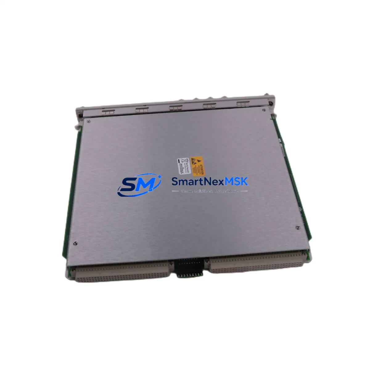
The Bently Nevada 3500/64M 176449-05 is a high-performance dynamic pressure monitor module engineered for direct retrofit into the Bently Nevada 3500 Series machinery protection platform. As legacy installations age and OEM support for earlier dynamic pressure monitor variants becomes increasingly limited, the 3500/64M 176449-05 provides a verified, drop-in-compatible replacement path that preserves existing rack architecture, field wiring infrastructure, and software logic — eliminating unnecessary engineering rework and reducing unplanned downtime during system modernization projects.
This module is purpose-built to replace discontinued or end-of-life dynamic pressure monitoring cards within the 3500 Series platform. It supports direct installation into the standard 3500 Series rack backplane, maintaining full compatibility with the existing 3500/20 rack power supply and the 3500/01 or 3500/05 rack interface modules. Engineers undertaking a control cabinet upgrade or partial system refresh can install this module without modifying existing terminal block wiring, provided the transducer signal range and power supply voltage are confirmed prior to commissioning.
Each unit supplied by SMARTNEXMSK undergoes pre-shipment functional testing covering module initialization, channel response, and communication output verification. Units are dispatched with a 12-month warranty covering manufacturing defects and functional failure under normal operating conditions, supporting your site’s spare parts governance and long-term maintenance planning requirements.
Upgrade Compatibility Table
| Parameter | Details |
|---|---|
| Compatible Platform | Bently Nevada 3500 Series Machinery Protection System |
| Replaces / Upgrades | 3500/64 and earlier dynamic pressure monitor variants (discontinued) |
| Rack Interface | 3500 Series standard backplane; compatible with 3500/01 and 3500/05 rack interface modules |
| Power Supply Compatibility | 3500/20 rack power supply (24 VDC nominal); verify available capacity before installation |
| Communication Protocol | Modbus RTU / Modbus TCP; System 1 software integration supported |
| Terminal Block Wiring | Compatible with standard 3500 Series I/O terminal block format; field wiring reuse supported |
| Installation Requirement | Verify transducer type, signal range, and terminal block pinout before installation |
| Module Address Configuration | Required via System 1 or rack configuration software after physical installation |
| Commissioning Note | Alarm setpoints, channel scaling, and Modbus register map must be verified against original configuration record |
| Replacement Recommendation | Direct slot replacement for 3500/64 variants; confirm firmware revision compatibility with 3500/05 rack interface |
| Warranty | 12-Month Warranty — covers manufacturing defects and functional failure under normal operating conditions from date of shipment |
Retrofit Planning for Existing Automation Systems
Successful retrofit of the 3500/64M 176449-05 into an existing 3500 Series installation requires a structured pre-installation review. Engineers should begin by auditing the current rack configuration, confirming available slot positions within the 3500 Series rack, and verifying that the 3500/20 power supply has sufficient capacity to support the replacement module load. In multi-rack installations, the 3500/05 rack interface module must be checked for firmware compatibility with the incoming card before proceeding.
Terminal block wiring should be mapped against the original I/O drawing set before removal of the legacy module. The 3500/64M 176449-05 uses the same standard I/O terminal block format as earlier 3500 Series dynamic pressure cards, which simplifies field wiring reuse. However, transducer compatibility — particularly for dynamic pressure sensors connected via the 3500 Series I/O module — must be validated against the module’s input impedance and signal conditioning specifications before the system is energized.
For sites running Bently Nevada System 1 software, the module address must be reassigned within the rack configuration database after physical installation. This step is critical to ensure that alarm setpoints, trend data channels, and HMI display tags — typically mapped through the System 1 operator interface — continue to reflect accurate process values without requiring a full HMI screen rebuild. Sites using third-party SCADA or DCS platforms connected via Modbus TCP should verify that the register map for the replacement module matches the legacy configuration to avoid communication link disruption at the historian or alarm management layer.
In control cabinet upgrade projects where the 3500 Series rack is being relocated or the cabinet layout is being revised, engineers should also account for the 3500/15 power supply input module and any associated 3500 Series communication gateway modules that bridge the machinery protection network to the plant DCS. Replacing the dynamic pressure monitor card in isolation without reviewing the broader communication chain — including any Modbus RTU serial links or Ethernet-based System 1 connections — can result in silent data loss at the historian level.
For I/O expansion projects, the 3500/64M 176449-05 can coexist in the same rack with other 3500 Series modules including vibration monitors, temperature monitors, and relay output modules, provided slot assignments and power budgets are respected. Where the existing rack is at capacity, a supplementary 3500 Series expansion rack with its own 3500/20 power supply and 3500/01 rack interface module may be required to accommodate additional I/O channels. All modules should be functionally tested under simulated process conditions before the system is returned to live operation.
Sites undertaking a broader migration from legacy Bently Nevada hardware to a modernized control platform should also evaluate the role of the 3500/32 four-channel relay output module and the 3500/22M transient data interface in the overall system architecture. These components are frequently part of the same retrofit scope and should be sourced and staged in parallel with the dynamic pressure monitor replacement to avoid sequential delays during the outage window.
Downtime Control During System Migration
Minimizing production downtime during a dynamic pressure monitor replacement requires careful pre-staging and a disciplined hot-swap or planned-outage protocol. Where the process permits a brief controlled shutdown, the preferred approach is to export the full rack configuration from System 1 prior to module removal, preserving all alarm setpoints, channel scaling factors, and Modbus communication parameters. This configuration backup allows rapid restoration if the replacement module requires re-commissioning from a known baseline, and serves as the primary reference document for the management of change (MOC) record.
For sites where continuous monitoring is operationally critical, a parallel monitoring strategy using portable vibration and dynamic pressure analyzers can maintain process visibility during the module swap window. The 3500/64M 176449-05 is designed for rapid slot insertion and does not require rack power cycling in most configurations, reducing the physical swap time to under 15 minutes in well-prepared installations where the terminal block wiring and module address have been pre-confirmed.
After installation, the module should be verified against the original HMI display screens to confirm that all dynamic pressure trend channels are populating correctly and that no spurious alarms have been triggered by the configuration change. Communication link integrity between the 3500 Series rack and the plant DCS or historian — whether via Modbus TCP, OPC, or System 1’s native protocol — should be confirmed before the process is returned to full load. Where a 3500/92 communication gateway module is in use, the gateway configuration should be reviewed to ensure the new module’s data is correctly mapped to the upstream system.
All commissioning steps, including out-of-service testing, alarm setpoint verification, and communication link confirmation, should be documented as part of the site’s MOC record. Each unit shipped by SMARTNEXMSK undergoes pre-shipment functional testing to verify module initialization, channel response, and communication output prior to dispatch, reducing the risk of commissioning delays caused by infant-failure defects. Units are supplied with a 12-month warranty, supporting your site’s spare parts governance and maintenance planning requirements.
Retrofit Support FAQ
Q: Is the 3500/64M 176449-05 a direct drop-in replacement for the earlier 3500/64 dynamic pressure monitor?
A: In most 3500 Series rack configurations, yes. The module uses the same backplane slot format and I/O terminal block layout as earlier 3500/64 variants. However, engineers should verify the transducer type, signal range, and any site-specific configuration parameters in System 1 before completing the swap, as minor firmware or channel scaling differences may require adjustment during commissioning.
Q: What commissioning steps are required after installing the replacement module?
A: After physical installation, the module address must be confirmed or reassigned in the rack configuration software. Alarm setpoints, channel scaling, and Modbus communication register mappings should be verified against the original configuration record. A functional test under simulated or live process conditions — including HMI display verification and communication link confirmation — is recommended before returning the system to service.
Q: Can the module be installed without rewiring the existing terminal blocks?
A: In most cases, yes. The 3500/64M 176449-05 is compatible with the standard 3500 Series I/O terminal block wiring format. Existing field wiring can typically be reused without modification, provided the transducer signal type, wiring polarity, and input impedance are confirmed against the module’s input specifications prior to installation. Any deviations from the original wiring configuration should be documented in the site’s as-built drawing set.
Q: What does the 12-month warranty cover, and how is pre-shipment testing conducted?
A: The 12-month warranty covers manufacturing defects and functional failure under normal operating conditions from the date of shipment. Each unit undergoes pre-shipment functional testing covering module initialization, channel response, and communication output verification before dispatch. For warranty claims, technical support, or pre-sales compatibility inquiries, contact SMARTNEXMSK directly via the details below.
© 2026 SMARTNEXMSK. All rights reserved.
Original Source: https://smartnexmsk.com
Contact: sales@smartnexmsk.com | +86 18259474341


