Bently Nevada 3500/64M Maintenance-Ready Spare for 3500 Automation
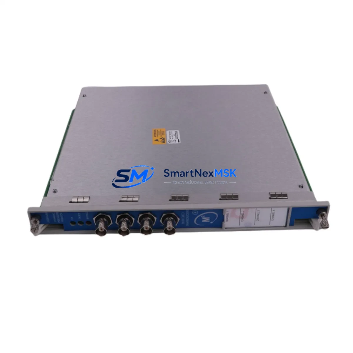
The Bently Nevada 3500/64M is a 4-channel dynamic pressure monitor module designed for continuous machinery protection within the 3500 Series rack-based monitoring system. For maintenance engineers managing rotating equipment — compressors, turbines, pumps, and fans — this module is a critical line-of-defence against undetected pressure excursions that can escalate into unplanned shutdowns. Sourced as an original spare, the 3500/64M is tested before shipment, supplied with a 12-month warranty, and stocked for fast global delivery to minimise downtime exposure on your site.
Whether you are executing a planned turnaround, responding to a fault alarm, or building a strategic spare parts inventory for an ageing 3500 Series rack, the 3500/64M demands careful integration planning. Maintenance and procurement engineers should treat this module replacement as an opportunity to audit the surrounding system — not just swap the card and close the work order.
Spare Maintenance Table
| Parameter | Specification / Detail |
|---|---|
| SKU / Part Number | 3500/64M |
| Brand | Bently Nevada |
| Series | 3500 Series Machinery Protection System |
| Module Type | Dynamic Pressure Monitor Module |
| Input Channels | 4-Channel |
| Measurement Type | Dynamic Pressure (pulsation, fluctuation monitoring) |
| Rack Compatibility | Bently Nevada 3500 Series rack (3500/20 Power Supply rack) |
| Communication | Rack backplane bus; compatible with 3500/22M Transient Data Interface |
| Operating Voltage | 24 VDC (supplied via 3500 rack backplane) |
| Operating Temperature | 0°C to +65°C (typical industrial panel environment) |
| Installation | DIN-rail rack slot insertion; no external wiring to module face |
| Application Environment | Compressor stations, turbine halls, pump skids, FPSO, petrochemical plant |
| Condition | Original spare; tested before shipment |
| Origin | United States |
| Warranty | 12 Months |
| Delivery | Fast global shipping; DHL / FedEx / air freight available |
Maintenance Planning for Continuous Operation
Replacing the 3500/64M in a live machinery protection rack is rarely a standalone task. A disciplined maintenance engineer will use the module swap as a trigger to inspect and verify the health of every component sharing the same rack slot group, power rail, and signal loop. Overlooking adjacent components is one of the most common causes of repeat faults after a module replacement.
Begin with the 3500/20 Power Supply module — the backbone of the entire rack. A degraded power supply delivering marginal voltage will stress a newly installed 3500/64M immediately. Check output voltage under load and inspect the capacitor bank for signs of bulging or discolouration. If the rack runs a redundant power configuration, verify that the standby 3500/20 switches over cleanly under a simulated supply failure.
Next, inspect the 3500/15 or 3500/16 rack interface module and the backplane connector pins for the slot adjacent to the 3500/64M. Bent or oxidised backplane pins are a frequent cause of intermittent communication faults that are misdiagnosed as module failures. Clean the connector with an appropriate contact cleaner and verify seating torque on the module ejector levers.
On the signal side, trace each of the four pressure transducer cables back to their field junction boxes. Inspect the pressure transducer connectors and cable shields for moisture ingress, chafing, or ground loops — all of which introduce noise that the 3500/64M will flag as a process alarm. Where transducers are approaching their rated service life, consider scheduling replacement of the pressure transducer assemblies during the same maintenance window to avoid a second outage within months.
The 3500/22M Transient Data Interface (TDI) module, if installed in the same rack, should be verified for firmware compatibility with the replacement 3500/64M. Mismatched firmware versions between the TDI and a newly installed monitor module can cause data dropouts in the historian or suppress alarm relay outputs. Confirm the rack’s System 1 software version and cross-reference the module firmware matrix before closing the work order.
For racks that also carry 3500/42M Proximitor/Seismic Monitor modules or 3500/45 Position Monitor modules, verify that the rack’s overall channel count and alarm relay assignments have not been disrupted by the module swap. The 3500 Series uses a slot-based relay mapping — inserting a replacement module in a different slot than the original will reassign relay outputs and may silently disable trip functions.
Finally, review the 3500/32 relay module outputs associated with the pressure monitor channels. Test each relay for correct trip setpoint response using the rack’s built-in self-test function. Document the as-found and as-left relay states in your maintenance management system. If the site uses a 3500/92 communication gateway for Modbus or OPC integration to the DCS or SCADA, confirm that the pressure channel data is being received correctly at the host system after the module is reinstated.
Site Replacement Workflow
Step 1 — Pre-replacement verification. Confirm the replacement 3500/64M SKU matches the installed module’s part number suffix (e.g., -01, -02 hardware revision). Mismatched hardware revisions may require a firmware update before the module will be accepted by the rack. Obtain the rack’s current configuration file from System 1 or the site DCS historian before removing the faulty module.
Step 2 — Bypass and inhibit. Place the affected channels into bypass mode via the rack keyswitch or System 1 software to prevent spurious trip signals during the swap. Notify the control room and obtain a permit-to-work before proceeding. For critical machinery, coordinate with operations to reduce load or bring the machine to a safe operating state.
Step 3 — Module removal and installation. Release the ejector levers, slide the faulty 3500/64M clear of the rack, and inspect the backplane connector for damage. Insert the replacement module firmly until the ejector levers engage. The rack will perform an automatic self-test sequence — observe the front-panel LEDs for the OK/Not OK status indication.
Step 4 — Configuration restore and verification. Download the saved configuration file to the replacement module via System 1. Verify all four channel setpoints, full-scale ranges, and alarm relay assignments match the as-designed values. Apply a known pressure signal to each channel using a portable pressure calibrator and confirm the module responds correctly across the full measurement range.
Step 5 — Return to service. Remove the bypass inhibit, confirm alarm relay outputs are live, and verify that the DCS or SCADA historian is receiving clean data on all four channels. Update the maintenance record with the replacement module serial number, firmware version, and calibration results. Retain the faulty module for failure analysis or return-to-vendor evaluation.
Stocking one 3500/64M as a cold spare — alongside a 3500/20 power supply and a 3500/32 relay module — provides a practical minimum spare holding for sites operating a single 3500 Series rack. For multi-rack installations or critical machinery trains, a hot-standby spare strategy with pre-configured modules is strongly recommended to achieve sub-one-hour mean time to restore.
Spare Parts Support FAQ
Q1: Is this 3500/64M an original Bently Nevada module or a third-party replacement?
This is an original Bently Nevada 3500/64M module — not a clone or third-party equivalent. All modules are sourced from authorised supply chains, inspected on receipt, and tested before shipment to confirm correct operation. A 12-month warranty is provided from the date of delivery.
Q2: How do I confirm compatibility with my existing 3500 Series rack before ordering?
Provide your rack’s system part number, the slot position of the existing module, and the hardware revision suffix from the module’s front-panel label. Our technical team will cross-reference the hardware and firmware matrix to confirm drop-in compatibility before the order is confirmed. We recommend sharing your System 1 configuration file or a photograph of the installed module label to eliminate any ambiguity.
Q3: What pre-shipment testing is performed on the 3500/64M?
Each module undergoes functional power-on testing, channel response verification, and communication bus check prior to packaging. Modules that do not pass all test criteria are quarantined and not shipped. A test report is available on request for quality-critical applications.
Q4: What is the recommended spare parts holding strategy for the 3500/64M?
For a single-rack installation, a minimum of one cold spare 3500/64M is recommended, stored in its original anti-static packaging in a climate-controlled environment. For multi-rack or safety-critical installations, consider maintaining a pre-configured hot spare with the site’s standard configuration file pre-loaded. Spare modules should be functionally tested annually and rotated into service on a planned basis to prevent shelf degradation of electrolytic components.
© 2026 SMARTNEXMSK. All rights reserved.
Original Source: https://smartnexmsk.com
Contact: sales@smartnexmsk.com | +86 18259474341


