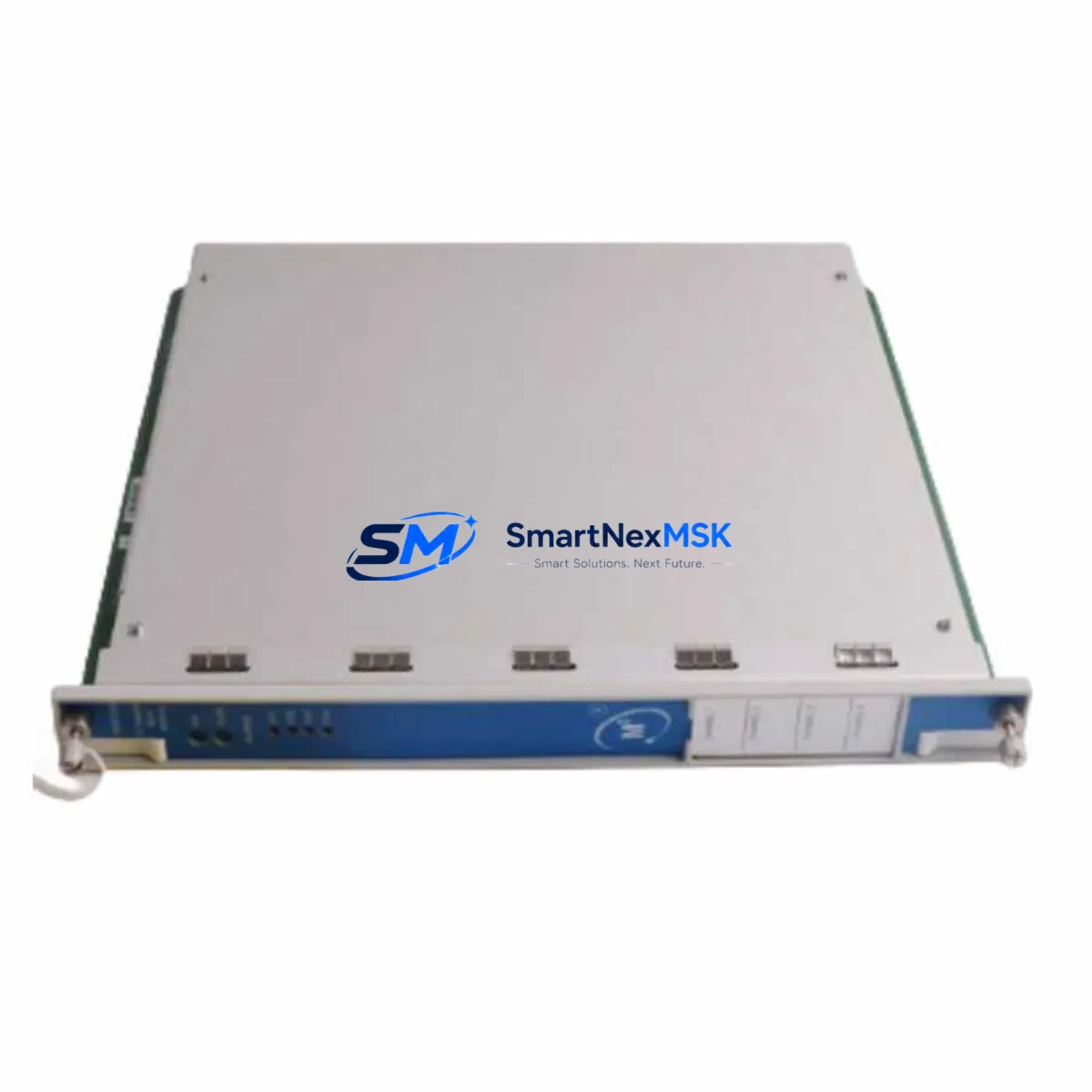
Bently Nevada 3500/70M 176449-09 Spare for 3500 Automation: Spare Replacement & Industrial Downtime Risk Control
The Bently Nevada 3500/70M 176449-09 is a Machinery Protection System (MPS) velocity monitor module designed for continuous vibration and velocity measurement within the 3500 Series modular protection rack. For maintenance engineers managing rotating equipment — turbines, compressors, pumps, and fans — this module is a critical line of defense against undetected mechanical faults. When this module fails or reaches end-of-life, the consequences extend beyond a single measurement point: the entire protection channel may go offline, leaving rotating machinery unmonitored and exposing the facility to unplanned shutdown risk.
Sourced as an original spare, the 3500/70M 176449-09 is pre-tested prior to shipment, verified for compatibility with the 3500 Series rack architecture, and backed by a 12-month warranty. Whether you are executing a planned overhaul, responding to a fault alarm, or building a strategic spare parts inventory for a long-running control system, this module ships ready for immediate installation.
Spare Maintenance Table
| Parameter | Specification / Detail |
|---|---|
| Part Number | 176449-09 |
| Model | 3500/70M |
| Brand | Bently Nevada |
| Series | 3500 Machinery Protection System |
| Module Type | MPS Velocity Monitor Module |
| Measurement | Velocity (seismic / shaft absolute) |
| Channels | 2-channel velocity monitoring |
| Input Signal | Velocity transducer (seismic probe compatible) |
| Rack Compatibility | Bently Nevada 3500 Series modular rack |
| Communication | Rack backplane bus; compatible with 3500/22M gateway |
| Power Supply | Supplied via 3500 rack power module (e.g. 3500/15) |
| Operating Temperature | 0°C to 65°C (standard industrial environment) |
| Origin | China (CN) |
| Condition | Original spare, pre-tested before shipment |
| Warranty | 12 Months |
| Shipping | Global express; DHL / FedEx / UPS available |
| Maintenance Recommendation | Inspect every 12–24 months; replace on alarm or drift |
Maintenance Planning for Continuous Operation
Replacing the 3500/70M 176449-09 is rarely an isolated task. In a well-maintained 3500 Series protection rack, a velocity monitor module replacement should trigger a systematic inspection of the surrounding protection chain. Maintenance engineers should verify the condition and calibration of the velocity transducers (seismic probes) wired to this module’s input terminals, as worn or improperly grounded probes will produce erroneous readings even with a new monitor installed.
The rack power module — typically a 3500/15 or equivalent — should be checked for output voltage stability and ripple, since an unstable power supply is a common root cause of spurious trips and module faults. Terminal blocks and field wiring connections at the I/O end should be inspected for corrosion, loose terminations, and insulation degradation, particularly in high-vibration or high-humidity environments.
If the 3500 rack includes a 3500/22M communication gateway module, its firmware version and network configuration should be confirmed compatible with the replacement monitor. Relay output modules within the same rack — such as the 3500/32 or 3500/33 — should be tested to confirm that trip relay logic responds correctly after the new module is commissioned. Signal isolators or barriers installed between the field transducer and the rack input should also be inspected; a degraded isolator can introduce signal offset that masks real machinery faults.
For facilities running extended maintenance intervals, it is advisable to hold at least one 3500/70M 176449-09 as a cold spare alongside other high-criticality modules such as the 3500/42M proximity monitor, 3500/45 position monitor, and 3500/50M tachometer module. A complete spare kit for a 3500 rack should also include the 3500/20 rack interface module and relevant I/O terminal blocks to support rapid swap-out during an emergency shutdown window.
For facilities with aging DCS or PLC integration, the 3500/22M Modbus or OPC gateway should be validated post-replacement to confirm that the new module’s channel data is correctly mapped to the historian or DCS alarm management system. This step is frequently overlooked and can result in silent data gaps in the condition monitoring record.
Site Replacement Workflow
Step 1 — Pre-replacement verification: Confirm the replacement module part number (176449-09) matches the installed module label. Cross-check the rack slot assignment in the system configuration documentation. Do not assume slot interchangeability without verifying the 3500 rack configuration file.
Step 2 — Safe isolation: Coordinate with the control room to place the affected channel in bypass or inhibit mode before removal. This prevents a spurious trip from propagating to the machinery protection relay chain during the swap.
Step 3 — Module removal and inspection: Remove the 3500/70M module from the rack. Inspect the backplane connector for bent pins or contamination. Clean with appropriate contact cleaner if required before inserting the replacement.
Step 4 — Installation and configuration: Insert the 3500/70M 176449-09 replacement module into the designated rack slot. Apply power and confirm the module passes its internal self-test (green status LED). Using Bently Nevada System 1 or the 3500 Rack Configuration Software, verify that all channel parameters — full-scale range, alert and danger setpoints, time delays, and transducer type — are correctly loaded from the saved configuration file.
Step 5 — Functional test: Apply a known reference signal to the velocity input and confirm the module’s displayed reading matches the expected value within calibration tolerance. Verify relay output response at the configured alert and danger thresholds.
Step 6 — Return to service: Remove the bypass/inhibit, confirm normal operation in the control room, and update the maintenance record with the replacement date, module serial number, and post-installation test results.
This workflow minimizes downtime, maintains system compatibility, and ensures the protection system is fully functional before the machinery is returned to load.
Spare Parts Support FAQ
Q1: Is the 3500/70M 176449-09 compatible with all 3500 Series rack configurations?
The 3500/70M 176449-09 is designed for the Bently Nevada 3500 modular rack platform. Compatibility depends on the rack’s power supply capacity and the slot assignment defined in the system configuration file. We recommend verifying your rack configuration file before ordering. Our technical team can assist with compatibility confirmation based on your rack model and existing module layout.
Q2: What pre-shipment testing is performed on this module?
Each 3500/70M 176449-09 unit undergoes functional verification prior to shipment, including power-on self-test confirmation and basic signal path verification. Units are packaged in anti-static protective packaging with inspection documentation. The 12-month warranty covers manufacturing defects and functional failures under normal operating conditions.
Q3: Can this module replace older or discontinued 3500/70 variants?
The 176449-09 option code designates a specific hardware and firmware configuration. Replacement of earlier 3500/70 or 3500/70M variants with different option codes should be validated against the system configuration file and Bently Nevada’s compatibility matrix. In many cases, the 176449-09 is a direct functional replacement, but configuration parameters may require adjustment in the rack software after installation.
Q4: What is your lead time and long-term supply availability for this part?
We maintain stock of the 3500/70M 176449-09 for immediate shipment. For facilities requiring long-term supply assurance — particularly those managing aging 3500 Series systems — we recommend establishing a blanket order or reserved stock arrangement. Contact our team to discuss multi-unit pricing, scheduled delivery, and extended supply agreements to support your maintenance planning cycle.
© 2026 SMARTNEXMSK. All rights reserved.
Original Source: https://smartnexmsk.com
Contact: sales@smartnexmsk.com | +86 18259474341


