Bently Nevada 3500/72M 176449-08 Retrofit-Ready Rod Drop Monitor: Compatible Modernization & Smooth Legacy System Upgrade
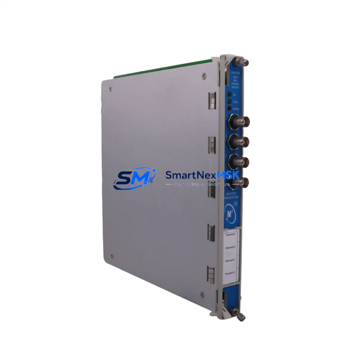
The Bently Nevada 3500/72M 176449-08 is a high-precision rod drop monitor module designed for continuous shaft position measurement in rotating machinery protection systems. As legacy Bently Nevada 3500 Series installations approach end-of-service milestones, plant engineers and reliability teams increasingly rely on this module — or its verified replacement — to sustain protection system integrity without full platform migration. Whether you are replacing a failed unit, upgrading a deteriorating rack assembly, or migrating from an older 3300 Series architecture, the 3500/72M 176449-08 delivers the compatibility, signal fidelity, and rack-level integration that critical machinery protection demands.
Upgrade Compatibility Table
| Parameter | Details |
|---|---|
| Compatible Rack | Bently Nevada 3500 Series Rack (3500/20 Power Supply required) |
| Installation Slot | Standard 3500 Series I/O slot; no rack modification required |
| Communication Compatibility | Modbus RTU, 3500 System Monitor interface |
| Replacement Recommendation | Direct replacement for 176449-08; verify transducer wiring polarity before installation |
| Commissioning Focus | Gap voltage calibration, OK relay setpoint verification, Keyphasor signal alignment |
| Warranty | 12-Month Warranty — covers module defects under normal operating conditions |
Retrofit Planning for Existing Automation Systems
Successful integration of the 3500/72M 176449-08 into an existing protection system begins well before the module arrives on site. Engineers should first audit the 3500 Series rack for available slot positions and confirm that the 3500/20 Power Supply module is delivering adequate rail voltage — typically +5 VDC and ±15 VDC — to support the additional monitor load. If the rack is near capacity, a rack expansion using a secondary 3500/05 Rack Interface Module may be required before installation proceeds.
Transducer wiring is the next critical checkpoint. The 3500/72M accepts input from Bently Nevada 3300 XL 8mm or 11mm proximity probes, and the existing field cable terminations must be verified against the module’s terminal block pinout. In many retrofit scenarios, the original 3300 Series monitor used a different barrier configuration — particularly where Zener barriers or galvanic isolators were installed for hazardous area compliance. These barriers must be re-evaluated for compatibility with the 3500/72M’s input impedance specifications.
Module address configuration is handled via the 3500 System Monitor software. Before powering the new module, engineers should document the existing channel configuration — including gap voltage setpoints, direct vibration alarm thresholds, and OK relay logic — from the outgoing unit or from the original commissioning records. This data is essential for replicating protection logic in the replacement module without inadvertently altering alarm trip levels.
Where the 3500 rack communicates upstream to a DCS or SCADA platform via Modbus RTU through a 3500/92 Communication Gateway, the gateway’s register map must be reviewed to confirm that the rod drop channel data addresses remain consistent after module swap. Any changes to slot assignment within the rack will shift the Modbus register offset and require a corresponding update in the DCS tag database — a step that is frequently overlooked and can result in silent data loss at the historian level.
HMI screens tied to the 3500 System Monitor or to a third-party operator interface should be reviewed for rod drop trend displays and alarm annunciation panels. If the plant uses a GE iFIX, Wonderware InTouch, or Ignition SCADA platform, the OPC DA or OPC UA tag paths referencing the rod drop channel must be validated post-swap to ensure continuous data flow to the control room.
For plants migrating from the older Bently Nevada 3300 Series platform entirely, the 3500/72M 176449-08 is a key component in a phased migration strategy. The 3300 Series rack, power supply, and I/O modules are retired in stages, with the 3500 rack and its associated 3500/01 Rack Interface Module, 3500/20 Power Supply, and 3500/22M Transient Data Interface installed in parallel before cutover. This approach preserves protection coverage during the transition and allows loop checks to be completed on the new system while the old system remains in service.
Downtime Control During System Migration
Minimizing unplanned downtime during a rod drop monitor replacement requires a structured pre-outage preparation protocol. All replacement modules — including the 3500/72M 176449-08 — should be bench-tested and gap-voltage verified before the maintenance window opens. A pre-configured spare, loaded with the correct setpoints and verified against the system’s protection logic documentation, can reduce in-rack commissioning time to under 30 minutes for a straightforward swap.
Original program logic stored in the 3500 System Monitor configuration file (.cfg) should be backed up to a secure engineering workstation before any hardware change. This file contains all channel configurations, alarm setpoints, OK relay logic, and Keyphasor assignments. Restoring from a verified backup eliminates the risk of manual re-entry errors and ensures that protection logic is identical to the pre-outage state.
Field control continuity during the swap can be maintained by temporarily bypassing the rod drop channel in the DCS interlock logic — with appropriate management of change documentation and operator awareness — so that a brief OK relay dropout during module seating does not trigger an unintended machine trip. Once the new module is seated, powered, and gap voltage confirmed within the acceptable window, the bypass is removed and the channel is returned to normal protection service.
Retrofit Support FAQ
Q1: Is the 3500/72M 176449-08 a direct drop-in replacement for the original module?
A: Yes, the 176449-08 is a slot-compatible replacement within the 3500 Series rack. No rack modification is required. Verify transducer cable terminations and gap voltage setpoints before powering the replacement unit.
Q2: What commissioning steps are required after installation?
A: After seating the module, connect to the 3500 System Monitor software, load the saved configuration file, verify gap voltage on each channel, confirm OK relay status, and perform a functional check of alarm setpoints. Document all readings in the commissioning record.
Q3: Can this module be used with 3300 Series proximity probes already installed in the field?
A: The 3500/72M is designed for use with Bently Nevada proximity probe systems. Compatibility with existing 3300 XL probes depends on cable length, extension cable type, and driver configuration. A loop calibration check is recommended before returning the channel to protection service.
Q4: What does the 12-month warranty cover?
A: The 12-month warranty covers manufacturing defects and functional failures under normal operating conditions. It does not cover damage resulting from incorrect installation, overvoltage, or environmental exposure beyond the module’s rated specifications. All units are functionally tested prior to shipment.
© 2026 SMARTNEXMSK. All rights reserved.
Original Source: https://smartnexmsk.com
Contact: sales@smartnexmsk.com | +86 18259474341


