Bently Nevada 3500/72M Maintenance-Ready Spare for 3500 Series Automation
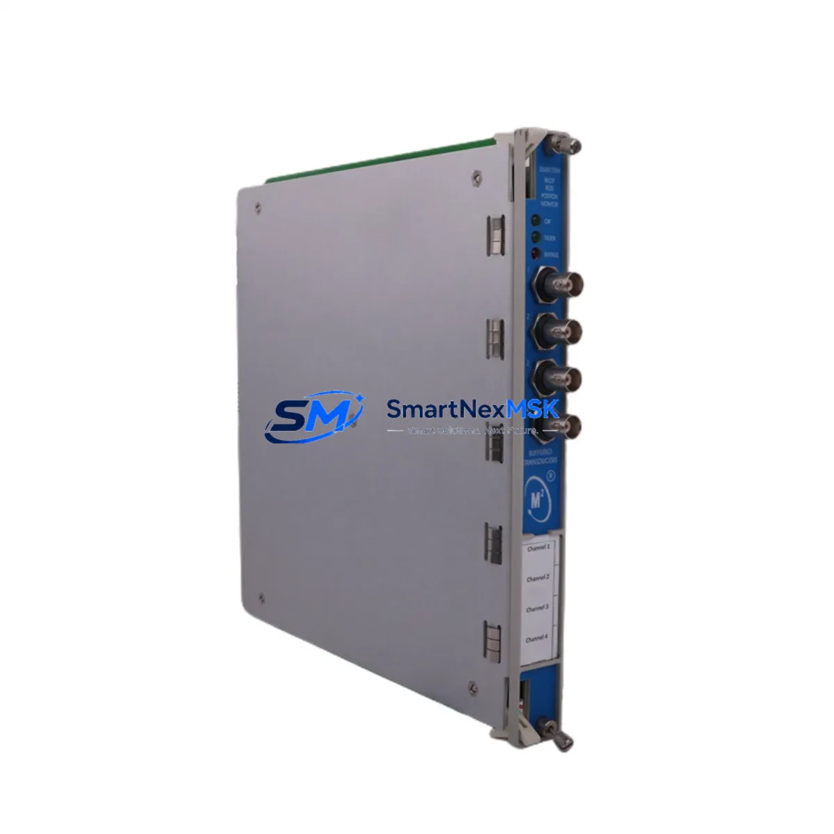
The Bently Nevada 3500/72M Reciprocating Rod Position Monitor is a precision condition monitoring module engineered for continuous operation in critical rotating and reciprocating machinery protection systems. As an original spare part sourced for the 3500 Series platform, this module is a cornerstone component for maintenance engineers managing compressor trains, turbine protection panels, and multi-channel vibration monitoring cabinets in oil & gas, petrochemical, and power generation facilities.
Unplanned downtime caused by a failed rod position monitor can cascade into full compressor shutdown, production loss, and costly emergency mobilization. Stocking a verified 3500/72M spare eliminates this risk. This unit ships fully tested, with all channel outputs verified against factory specifications, and is backed by a 12-month warranty — giving procurement and maintenance teams the confidence to execute planned replacements or emergency swap-outs without delay.
Whether you are executing a scheduled turnaround, responding to a channel fault alarm, or building out your critical spare inventory for a long-term asset management program, the 3500/72M is a direct, plug-compatible replacement for existing 3500 Series rack installations.
Spare Maintenance Table
| Parameter | Specification / Detail |
|---|---|
| SKU / Part Number | 3500/72M |
| Brand | Bently Nevada |
| Series | 3500 Series Machinery Protection System |
| Module Type | Reciprocating Rod Position Monitor |
| Channels | 2-channel rod drop / position monitoring |
| Input Signal | Eddy-current proximity probe (3300 XL / 7200 Series compatible) |
| Output | 4–20 mA analog, relay outputs, Keyphasor interface |
| Communication | 3500 rack backplane bus; optional TDI/System 1 integration |
| Power Supply | Supplied via 3500/15 or 3500/20 power module (rack-mounted) |
| Operating Temperature | 0°C to 65°C (32°F to 149°F) |
| Mounting | 3500 Series standard rack slot (2-slot module) |
| Compatibility | 3500/01, 3500/05, 3500/22M, 3500/25, 3500/40M, 3500/42M, 3500/45, 3500/50M racks |
| Condition | Original spare — tested prior to shipment |
| Warranty | 12 months from date of shipment |
| Application Environment | Reciprocating compressors, gas turbines, steam turbines, industrial rotating machinery |
| Maintenance Recommendation | Replace on channel fault alarm, rod drop alarm, or during scheduled turnaround; verify probe gap and cable continuity before installation |
Maintenance Planning for Continuous Operation
When a 3500/72M fault is identified during routine control cabinet inspection or triggered by a System 1 alarm, the replacement workflow should extend beyond the module itself. Maintenance engineers should treat this event as an opportunity to audit the full measurement chain and adjacent protection circuits.
Begin with the proximity probe and extension cable — typically a 3300 XL 8mm or 3300 XL 11mm eddy-current probe paired with a matched extension cable and a 3300 XL proximitor/driver. A degraded probe or cable with micro-fractures will cause the replacement 3500/72M to generate erratic readings immediately after installation, masking the true repair. Verify probe gap (typically 1.0–2.5 mm depending on target material) with a calibrated gap meter before closing the cabinet.
Next, inspect the 3500 rack power supply — the 3500/15 Power Supply or 3500/20 Power Supply module. A marginal power module operating near its load limit can cause intermittent faults across multiple monitor modules, including the 3500/72M, the 3500/22M Transient Data Interface, and the 3500/40M Proximitor/Seismic Monitor. Confirm DC output voltage and ripple are within specification.
For compressor protection panels, also inspect the 3500/32 4-Channel Relay Module and the 3500/33 16-Channel Relay Module. These relay modules execute the trip and alarm logic driven by the 3500/72M rod position data — a failed relay contact can prevent a valid trip signal from reaching the compressor shutdown system, creating a latent safety risk that only surfaces during an actual overstress event.
If the 3500 rack is integrated with a DCS or safety system via the 3500/92 Communication Gateway Module, verify that the Modbus or OPC-DA data path is intact after module replacement. A rack reset following module swap can temporarily interrupt the communication gateway, causing false “module offline” alarms at the DCS operator station. Coordinate with the control room before executing the swap.
Finally, review the terminal block wiring and I/O marshalling at the field junction box. Loose terminations on the rod position signal wiring are a common root cause of nuisance alarms that are incorrectly attributed to module failure. Torque all terminals to specification and inspect for corrosion, especially in humid or offshore environments.
Site Replacement Workflow
Step 1 — Pre-Replacement Verification: Confirm the replacement 3500/72M firmware revision matches or is compatible with the existing rack configuration file. Mismatched firmware can prevent the module from being recognized by the rack processor (3500/05 or 3500/01). Download the current rack configuration using System 1 or the 3500 Rack Configuration Software before pulling the faulty module.
Step 2 — Safe Module Removal: The 3500 Series supports hot-swap of monitor modules without full rack power-down, provided the rack is configured for online replacement. Verify this setting in the rack configuration before proceeding. If hot-swap is not enabled, coordinate a controlled shutdown with the operations team to minimize unplanned downtime.
Step 3 — Module Installation and Configuration Restore: Seat the 3500/72M firmly into the rack slot, ensuring the backplane connector is fully engaged. Restore the saved rack configuration file. The module will self-initialize and begin outputting rod position data within 30–60 seconds of configuration load.
Step 4 — Channel Verification: Using System 1 or a handheld calibrator, verify that both rod position channels are reading within the expected range for the current machine operating state. Confirm alarm and trip setpoints are active and match the approved protection philosophy document.
Step 5 — Documentation: Record the replacement in the plant CMMS (SAP PM, Maximo, or equivalent), including the removed module serial number, replacement module serial number, date, technician, and post-replacement channel readings. This record supports warranty claims and future failure trend analysis.
Spare Parts Support FAQ
Q1: Is this 3500/72M an original Bently Nevada module or a third-party equivalent?
This is an original Bently Nevada 3500/72M module. It is not a clone, aftermarket reproduction, or third-party equivalent. All units are sourced from authorized channels and tested prior to shipment to verify channel output, communication, and relay function.
Q2: What is the warranty coverage and what does it include?
Every 3500/72M ships with a 12-month warranty from the date of shipment. The warranty covers manufacturing defects and functional failures under normal operating conditions. It does not cover damage caused by incorrect installation, overvoltage, or physical impact. Warranty claims are processed with return shipping support.
Q3: How do I confirm compatibility with my existing 3500 rack before ordering?
Provide your rack model number (e.g., 3500/05 or 3500/01), current firmware revision, and rack configuration file version. Our technical team will confirm slot compatibility, firmware alignment, and any configuration considerations before shipment. This pre-shipment compatibility check is included at no additional cost.
Q4: What is the typical lead time and how is the module packaged for shipment?
In-stock units ship within 1–3 business days. Each module is individually packaged in anti-static ESD shielding, foam-lined carton, and labeled with the part number, serial number, and test certification. Express and freight forwarding options are available for urgent maintenance requirements.
© 2026 SMARTNEXMSK. All rights reserved.
Original Source: https://smartnexmsk.com
Contact: sales@smartnexmsk.com | +86 18259474341


