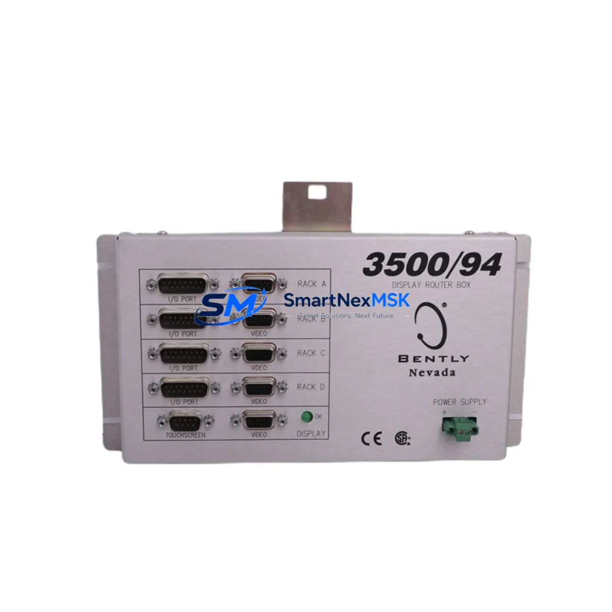
Bently Nevada 3500/94 145988-01 Retrofit-Ready Display Router Module for 3500 Series Control Systems
The Bently Nevada 3500/94 145988-01 is a Display Router Module engineered for the 3500 Series machinery protection and condition monitoring platform. As legacy 3500 Series installations age and original components approach end-of-life, the 3500/94 145988-01 serves as a direct retrofit-ready replacement that preserves existing rack architecture, wiring infrastructure, and software configuration without requiring a full system overhaul. This module routes display data between the 3500 rack backplane and connected operator interface devices, maintaining real-time vibration, position, and process variable visualization across the control network.
For facilities managing rotating machinery — including turbines, compressors, pumps, and generators — the 3500/94 145988-01 provides a reliable upgrade path that minimizes engineering rework. The module slots directly into the standard 3500 Series 19-inch rack alongside components such as the 3500/15 Power Supply Module, 3500/20 Rack Interface Module, 3500/22M Transient Data Interface, and 3500/40M Proximitor/Seismic Monitor. Its backplane interface is fully compatible with the existing rack bus, eliminating the need for rewiring terminal blocks or reconfiguring I/O channel assignments.
When replacing a failed or obsolete display router in an active installation, engineers should verify the rack slot address assignment, confirm backplane connector seating, and validate communication link continuity to the 3500/95 Display Interface Module if present in the same rack. The 3500/94 145988-01 supports the same communication protocol stack as its predecessors, ensuring that existing System 1 Evolution software configurations, alarm setpoints, and trend data archives remain intact post-swap.
Upgrade Compatibility Table
| Parameter | Details |
|---|---|
| SKU / Part Number | 3500/94 145988-01 |
| Series Compatibility | Bently Nevada 3500 Series Machinery Protection System |
| Module Type | Display Router Module |
| Rack Installation | Standard 3500 Series 19-inch rack, backplane slot mount |
| Backplane Interface | Compatible with 3500 Series rack bus; no rewiring required |
| Communication Protocol | 3500 Series internal bus; compatible with System 1 Evolution software |
| Direct Replacement For | Obsolete / failed 3500/94 variants; legacy display router configurations |
| Retrofit Recommendation | Verify slot address, backplane seating, and display link continuity before power-on |
| Commissioning Notes | Confirm alarm setpoints, trend archives, and HMI display mapping post-installation |
| Warranty | 12-Month Warranty — covers manufacturing defects and functional failure |
| Origin | USA (Bently Nevada / Baker Hughes) |
| Condition | New / Refurbished / Tested — specify at order |
Retrofit Planning for Existing Automation Systems
Successful retrofit of the 3500/94 145988-01 into an operating facility requires systematic pre-installation planning. Begin by auditing the existing rack configuration: document all occupied slots, confirm the 3500/15 Power Supply Module output capacity, and verify that available power budget accommodates the display router’s draw without exceeding the rack’s total load rating. In multi-rack installations, the 3500/20 Rack Interface Module governs inter-rack communication; confirm that its firmware revision is compatible with the replacement display router before proceeding.
Terminal block wiring on adjacent I/O modules — such as the 3500/40M Proximitor/Seismic Monitor or the 3500/42M Proximitor/Seismic Monitor — should be photographed and labeled prior to any rack disturbance. Even though the 3500/94 145988-01 does not directly interface with field wiring, adjacent module removal during installation can disturb terminal connections if not properly secured. Use the 3500 Series Rack Installation and Maintenance manual to confirm torque specifications for backplane connector screws.
For facilities that have integrated the 3500 rack with a DCS or SCADA platform via the 3500/22M Transient Data Interface or a Modbus/TCP gateway, validate that the display routing path does not interrupt the data acquisition chain during module hot-swap or cold-swap procedures. Where hot-swap is not supported, coordinate with the control room to place affected channels in bypass mode using the 3500/20 Rack Interface Module’s bypass function, preventing spurious trips during the swap window.
HMI screens connected to the 3500 platform — whether running System 1 Evolution, Bently Nevada System 1 Classic, or a third-party SCADA — should be verified for display tag mapping after the 3500/94 145988-01 is seated and powered. Confirm that all channel labels, engineering unit conversions, and alarm threshold displays are rendering correctly before releasing the system back to operations. Programming cables such as the 3500 Series RS-232 configuration cable may be required to re-confirm module address settings if the replacement unit ships with factory-default configuration.
Downtime Control During System Migration
Minimizing unplanned downtime during a display router replacement on a live 3500 Series rack requires a structured change management approach. First, schedule the swap during a planned maintenance window aligned with the facility’s rotating equipment inspection cycle. Coordinate with operations to confirm that the machinery monitored by the affected rack channels — turbines, compressors, or pump trains — can be safely placed in a monitored bypass state for the duration of the swap.
Before removing the 3500/94 145988-01 (failed unit), export the full rack configuration from System 1 Evolution or the 3500 Rack Configuration Software. This configuration file preserves channel assignments, transducer scale factors, alarm setpoints, and communication parameters. If the replacement module requires re-flashing or address configuration, this file serves as the authoritative restore point, eliminating the need to manually re-enter hundreds of parameters under time pressure.
During installation, follow the ESD (electrostatic discharge) handling protocol specified in the 3500 Series hardware manual. Seat the module firmly into the backplane, secure the front-panel locking screws, and restore rack power in the sequence recommended by Bently Nevada: power supply first, rack interface module second, then monitor and display modules. This sequence prevents backplane bus contention and protects the integrity of the communication link between the 3500/94 145988-01 and connected display devices.
After power-on, allow the module a full initialization cycle (typically 30–60 seconds) before verifying display output. Confirm that all monitored channels are reporting live values, that no fault LEDs are illuminated on adjacent modules, and that the System 1 Evolution trend display is receiving updated data. Document the completed swap in the facility’s maintenance management system and retain the replaced module for failure analysis if required.
Retrofit Support FAQ
Q1: Is the 3500/94 145988-01 a direct drop-in replacement for all 3500/94 variants?
The 3500/94 145988-01 is designed as a direct replacement for the standard 3500/94 Display Router Module family. Minor firmware or hardware revision differences between sub-variants may exist; confirm the revision level of the unit being replaced against the replacement unit’s documentation before installation. In most cases, the module is functionally interchangeable within the 3500 Series rack without software reconfiguration.
Q2: What commissioning steps are required after installation?
After seating the module and restoring rack power, verify backplane communication status via the 3500/20 Rack Interface Module’s status indicators. Reload the saved rack configuration file if the replacement unit was shipped with factory defaults. Confirm display output on all connected HMI screens, validate alarm setpoint integrity in System 1 Evolution, and perform a channel-by-channel live signal check using a calibrated signal source if the installation schedule permits.
Q3: Can the 3500/94 145988-01 be used in racks running mixed-generation 3500 Series modules?
Yes. The 3500 Series platform is designed for backward compatibility across module generations within the same rack. The 3500/94 145988-01 will coexist with earlier-generation monitor modules, power supplies, and interface modules in the same rack without requiring a full rack upgrade. Verify firmware compatibility between the display router and the rack interface module if mixing modules from significantly different production periods.
Q4: What does the 12-month warranty cover, and what is the return process?
The 12-month warranty covers manufacturing defects and functional failure under normal operating conditions. It does not cover damage resulting from incorrect installation, overvoltage, or physical mishandling. To initiate a warranty claim, contact our sales team with the order number, module serial number, and a description of the fault. We will arrange return shipping and provide a tested replacement or full refund upon fault verification. Pre-shipment functional testing is performed on all units before dispatch.
© 2026 SMARTNEXMSK. All rights reserved.
Original Source: https://smartnexmsk.com
Contact: sales@smartnexmsk.com | +86 18259474341


