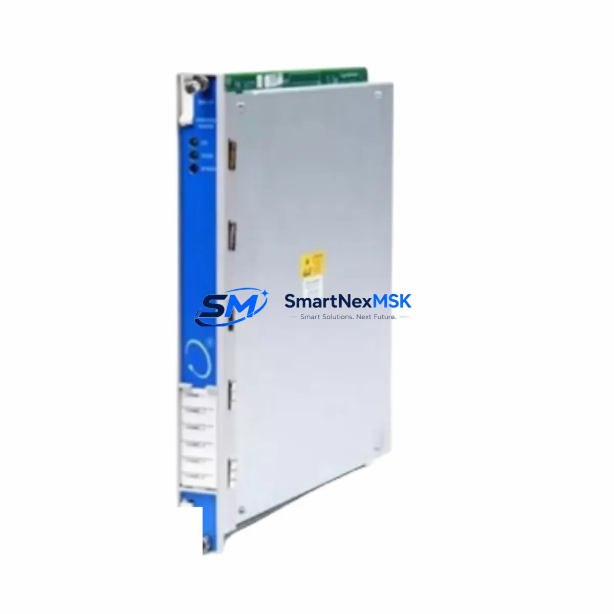
Bently Nevada 3500/94M 184826-01 Retrofit-Ready Display Monitor for 3500 Series Control Systems
The Bently Nevada 3500/94M 184826-01 is a retrofit-ready display monitor engineered for seamless integration into existing 3500 Series Machinery Protection System (MPS) racks. As legacy 3500/94 and earlier 3500-series display units reach end-of-life or become increasingly difficult to source, the 3500/94M 184826-01 provides a validated drop-in upgrade path that preserves existing wiring infrastructure, rack slot assignments, and communication links — minimizing engineering rework and unplanned downtime during system modernization.
This module is designed for industrial facilities operating rotating machinery monitoring systems, including turbines, compressors, pumps, and generators, where continuous vibration and process data display is mission-critical. Engineers planning a control cabinet upgrade or a full MPS rack refresh will find the 3500/94M 184826-01 compatible with the standard 3500 Series backplane, supporting the same terminal block wiring conventions used across the 3500/20 rack controller, 3500/22M transient data interface, and 3500/42M proximitor/seismic monitor modules.
Upgrade Compatibility Table
| Parameter | Details |
|---|---|
| Replaces / Upgrades | Bently Nevada 3500/94, 3500/94M (earlier revisions) |
| Rack Compatibility | 3500 Series standard 19-slot rack; backplane slot assignment preserved |
| Communication Interface | RS-232 / RS-485 serial; compatible with existing System 1 and TDXnet communication links |
| Wiring Compatibility | Terminal block pinout compatible with prior 3500/94 installations; no rewiring required in most retrofit scenarios |
| Power Supply Requirement | Powered via 3500 Series rack backplane; verify 3500/15 or 3500/15E power supply capacity before installation |
| Installation Requirement | Standard DIN rail / rack slot insertion; firmware configuration via System 1 software |
| Retrofit Recommendation | Recommended for direct replacement of discontinued 3500/94 display units; verify firmware revision compatibility |
| Commissioning Notes | Confirm module address assignment, display channel mapping, and alarm setpoint transfer from legacy configuration |
| Warranty | 12-Month Warranty — covers manufacturing defects and functional failures under normal operating conditions |
Retrofit Planning for Existing Automation Systems
A successful retrofit of the 3500/94M 184826-01 into an operational MPS rack requires systematic pre-installation planning. Before removing the legacy display module, engineers should document the existing channel configuration, alarm setpoints, and display group assignments stored in the 3500/20 rack controller. The 3500/20 rack controller retains system-level configuration data and serves as the primary communication gateway between the display module and the plant DCS or SCADA layer.
Power budget verification is a critical first step. The 3500/15 or 3500/15E power supply module must have sufficient headroom to support the 3500/94M 184826-01 alongside other installed modules such as the 3500/40M proximitor monitor, 3500/42M proximitor/seismic monitor, and 3500/45 position monitor. Overloading the rack power supply is a common cause of intermittent faults during post-retrofit commissioning.
Terminal block wiring should be verified against the original installation drawings. In most 3500 Series installations, the display module connects to the rack backplane without field wiring, but any external serial communication cables connecting to a System 1 workstation or a Modbus RTU gateway should be inspected for continuity and correct pinout before powering up the replacement module.
For facilities migrating from older System 1 software versions, confirm that the host workstation running the condition monitoring platform supports the firmware revision embedded in the 3500/94M 184826-01. In some cases, a firmware update to the 3500/22M transient data interface or the 3500/60 temperature monitor may be required to maintain full system interoperability after the display module is replaced.
HMI screen updates are often overlooked during MPS retrofit projects. If the plant HMI is configured to poll display data from the 3500/94 via a serial link or OPC server, the communication driver configuration must be updated to reflect the new module’s firmware version and any changes in data register mapping. Coordinate with the DCS or SCADA team to validate that all alarm and trend displays on the operator workstation reflect accurate data after the retrofit is complete.
For facilities using a 3500/32 relay module or 3500/33 16-channel relay module for alarm output, verify that the relay trip setpoints and latching behavior are correctly transferred to the new configuration. These relay modules interact directly with the monitoring channels managed by the display system, and any misconfiguration can result in spurious trips or missed alarms during the initial post-retrofit operating period.
Downtime Control During System Migration
Minimizing production downtime during an MPS display module replacement requires a structured hot-swap or planned outage strategy. Where the process permits a brief controlled shutdown, the preferred approach is to place the 3500 Series rack into bypass mode using the rack controller’s inhibit function, swap the 3500/94M 184826-01 into the designated slot, restore power, and perform a rapid configuration verification before releasing the bypass.
For critical rotating machinery where even brief monitoring gaps are unacceptable, a parallel monitoring arrangement using a portable vibration analyzer connected to the existing proximitor probes can maintain continuous protection during the module exchange. This approach is particularly important for high-speed turbine trains where the 3500/40M or 3500/42M proximitor monitors are providing active overspeed and radial vibration protection.
After installation, the commissioning sequence should include: power-on self-test verification, channel-by-channel display validation against known reference signals, alarm setpoint confirmation, and a communication link test to the System 1 workstation or DCS gateway. Retain the original 3500/94 module as a tested spare until the replacement has completed a full operational cycle, typically 72 hours of continuous monitored operation, to confirm stable performance before declaring the retrofit complete.
All units supplied by SMARTNEXMSK are pre-tested prior to shipment. Each 3500/94M 184826-01 undergoes functional verification to confirm display operation, communication interface integrity, and backplane connector condition. This pre-shipment testing significantly reduces the risk of commissioning delays caused by infant-mortality failures in replacement hardware.
Retrofit Support FAQ
Q1: Is the 3500/94M 184826-01 a direct drop-in replacement for the original 3500/94 display monitor?
In the majority of 3500 Series rack installations, yes. The 3500/94M 184826-01 occupies the same rack slot, uses the same backplane interface, and maintains the same external communication pinout as the original 3500/94. However, customers should verify the firmware revision compatibility with their installed System 1 software version before installation, as some older System 1 releases may require an update to fully support the 184826-01 revision.
Q2: What wiring changes are required during installation?
In most retrofit scenarios, no field wiring changes are required. The 3500/94M 184826-01 connects to the rack backplane directly. Any external serial communication cables (RS-232 or RS-485) connecting to a System 1 workstation or Modbus gateway should be inspected and confirmed to be correctly terminated before powering up the new module. If the existing cable uses a non-standard pinout, a wiring adapter may be required.
Q3: How do I transfer alarm setpoints and channel configuration from the old module to the new one?
Alarm setpoints and channel configuration for the 3500 Series are stored in the 3500/20 rack controller, not in the display module itself. When the 3500/94M 184826-01 is installed and powered, it will read the existing configuration from the rack controller automatically. Customers should verify the displayed values against the original configuration documentation after power-up to confirm correct data transfer.
Q4: What does the 12-month warranty cover, and what is the return process?
The 12-month warranty covers manufacturing defects and functional failures under normal operating conditions from the date of shipment. It does not cover damage caused by incorrect installation, overvoltage, or physical mishandling. To initiate a warranty claim, contact SMARTNEXMSK at sales@smartnexmsk.com with the order reference and a description of the fault. Replacement or repair will be arranged within the warranty period at no additional cost.
© 2026 SMARTNEXMSK. All rights reserved.
Original Source: https://smartnexmsk.com
Contact: sales@smartnexmsk.com | +86 18259474341


