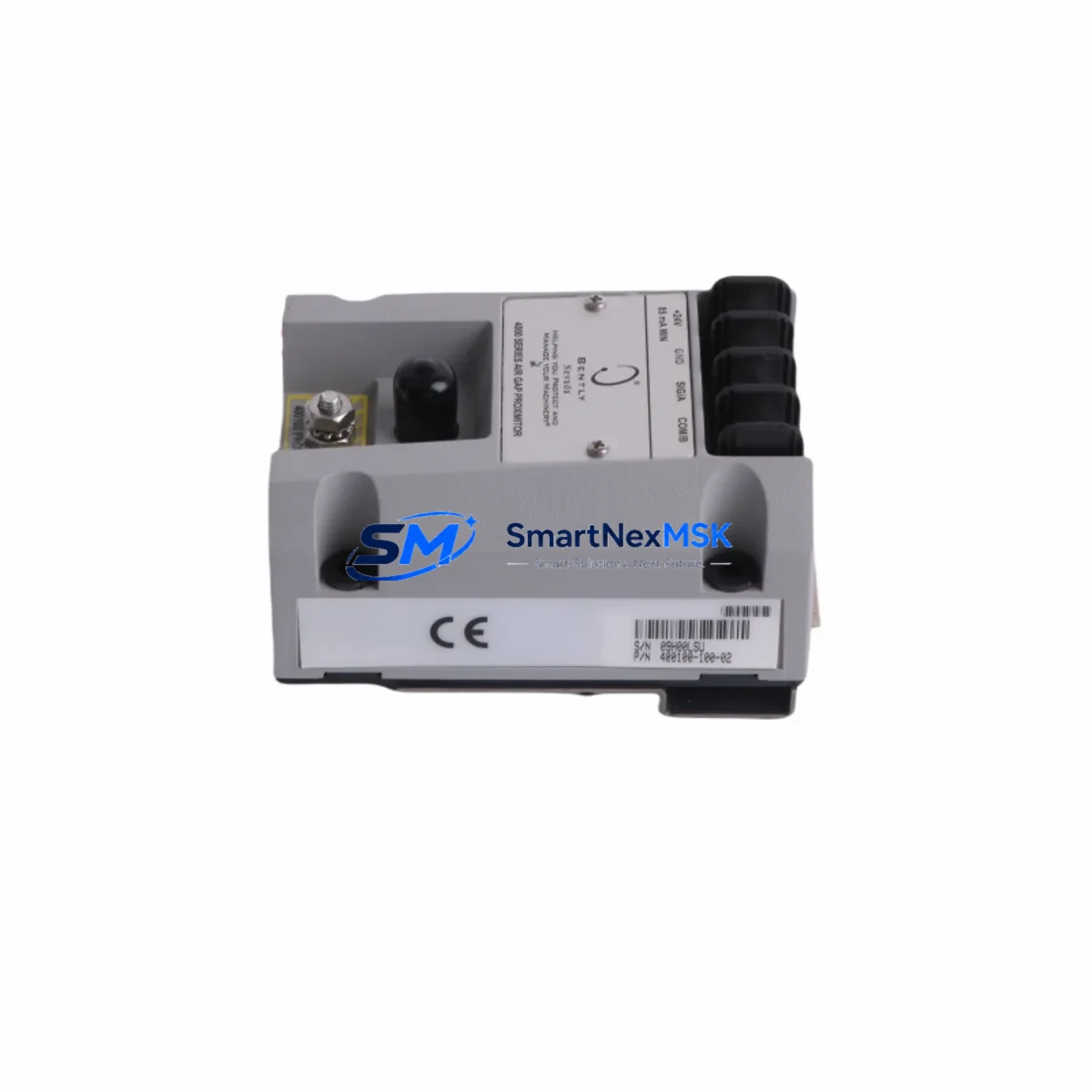
Bently Nevada 400100-100-02 Retrofit-Ready Proximity Probe for 3300 XL Control Systems
The Bently Nevada 400100-100-02 is a high-precision eddy-current proximity probe engineered for seamless integration into existing 3300 XL Series vibration monitoring systems. As legacy Bently Nevada installations age and OEM support windows narrow, plant engineers and reliability teams increasingly require verified drop-in replacements that preserve signal integrity, maintain system calibration, and eliminate the need for full rack overhauls. The 400100-100-02 addresses exactly this need — delivering a retrofit-ready solution that slots directly into your existing 3300 XL monitor rack without rewiring, recalibration of the full channel, or modification of existing Proximitor® sensor assemblies.
Whether you are managing a planned outage, responding to an unplanned probe failure, or executing a phased modernization of your rotating machinery protection system, the 400100-100-02 provides the dimensional accuracy, gap voltage linearity, and cable impedance characteristics required by the 3300 XL 8mm Proximitor® System. It is compatible with standard 3300 XL monitor cards including the 3300/16 Dual Voting and 3300/20 Radial Vibration monitor modules, and integrates without firmware changes when used within the validated gap range of 0.25 mm to 2.25 mm.
Before installing a replacement probe in a live system, engineers should verify the following parameters against the existing installation baseline: power supply voltage at the Proximitor® driver (typically –24 VDC), terminal block wiring polarity and shield grounding at the junction box, extension cable length and impedance (the 330130 series extension cables are the standard pairing), probe gap voltage at the target shaft surface (nominal –10 VDC at mid-gap), monitor card address and channel assignment within the 3500 or 3300 rack, and DCS or historian tag mapping to ensure the replacement channel is correctly identified in the control narrative. Where the existing system interfaces with a System 1® Evolution software platform, probe replacement should be followed by a channel verification step within the software to confirm alarm setpoints and OK relay logic remain intact.
Upgrade Compatibility Table
| Parameter | 400100-100-02 Specification | Retrofit Notes |
|---|---|---|
| Probe Type | Eddy-Current, 8 mm tip diameter | Direct replacement for standard 3300 XL 8 mm probe assemblies |
| Compatible Monitor Series | Bently Nevada 3300 XL, 3500 Series | Verify monitor card firmware version ≥ 3.x for 3500 racks |
| Supply Voltage | –24 VDC (via Proximitor® driver) | Confirm power rail at junction box before installation |
| Gap Voltage Range | –2 VDC to –18 VDC (linear range: –10 VDC nominal) | Re-gap to –10 VDC ± 0.5 VDC after installation |
| Extension Cable Compatibility | 330130 Series (standard), 330180 Series (armored) | Do not mix cable series; impedance mismatch affects linearity |
| Installation Thread | M10 × 1.0 (standard 3300 XL bracket) | Reuse existing bracket; inspect threads before reinstallation |
| Communication / Integration | Analog 4–20 mA / OK relay output via monitor card | DCS tag mapping and historian configuration unchanged |
| Replacement Scope | Probe only (Proximitor® and cable sold separately) | Inspect Proximitor® driver (3300 XL 8mm) for concurrent replacement |
| Warranty | 12 Months | Covers manufacturing defects; excludes physical damage post-installation |
Retrofit Planning for Existing Automation Systems
A successful 400100-100-02 retrofit begins well before the maintenance window opens. Reliability engineers should pull the existing probe’s installation record to confirm the target material (typically 4140 steel or equivalent), shaft surface finish, and the original gap setting documented during commissioning. The 3300 XL 8mm Proximitor® sensor (driver module) should be inspected simultaneously — if the driver has accumulated more than 80,000 operating hours, concurrent replacement is strongly recommended to avoid a repeat outage within the same planning cycle.
For systems where the 400100-100-02 feeds into a 3500/42M Proximitor®/Seismic Monitor or a 3500/40M Proximitor® Monitor, the channel configuration stored in the rack’s non-volatile memory does not need to be re-entered, provided the replacement probe is of the same series and tip diameter. However, if the site is simultaneously migrating from a legacy 3300 Series rack to a 3500 Series rack as part of a broader control system upgrade, the full channel configuration — including OK limits, danger setpoints, and time-delay settings — must be re-entered via the Rack Configuration Software (RCS) or System 1® Evolution interface.
In multi-probe installations monitoring radial vibration on large rotating machinery (compressors, turbines, pumps), it is common to replace the X-Y probe pair simultaneously. The companion probe in an X-Y pair is typically a second 400100-100-02 or a 400100-100-01 (shorter cable assembly), depending on the bracket geometry. The 330130-080-00-00 extension cable is the standard 8-meter pairing for most compressor train installations, while the 330130-050-00-00 (5-meter) is common in smaller pump skids. Both are compatible with the 400100-100-02 without derating.
Where the existing control cabinet also houses a 3300/55 Keyphasor® Monitor or a 3500/25 Keyphasor® Module, the Keyphasor® signal does not require reconfiguration during a probe-only replacement. However, if the site is upgrading the full vibration monitoring rack and adding a 3500/22M Transient Data Interface for enhanced machinery diagnostics, the new TDI module must be configured to recognize the replacement probe’s channel assignment before the system is returned to service.
For plants running Emerson DeltaV or Honeywell Experion PKS as the primary DCS, the vibration monitor’s OK relay and analog output are typically hardwired to the DCS I/O marshalling cabinet. No DCS configuration changes are required for a like-for-like probe replacement, but the I/O loop check should be repeated as part of the post-installation commissioning checklist to confirm signal continuity from the probe tip through to the DCS historian tag.
Downtime Control During System Migration
Minimizing unplanned downtime during a proximity probe replacement requires a structured pre-outage preparation protocol. Before the maintenance window, the replacement 400100-100-02 should be bench-tested using a portable Proximitor® tester or a calibrated gap simulator to confirm the probe’s output voltage linearity across the full gap range. This pre-verification step eliminates the risk of installing a defective unit and extends the outage unnecessarily.
During the outage, the sequence should follow: (1) isolate the monitor channel and confirm the OK relay has de-energized at the DCS, (2) remove the existing probe without disturbing the extension cable connector at the junction box, (3) install the 400100-100-02 and set the gap to –10 VDC using a calibrated DC voltmeter at the Proximitor® output terminals, (4) restore the monitor channel and confirm the OK relay re-energizes within the expected time delay, and (5) verify the vibration reading at the DCS matches the baseline value recorded before the outage. This five-step sequence can typically be completed within 45–90 minutes per probe position, keeping total outage time well within a standard 4-hour maintenance window even for X-Y probe pair replacements.
For sites where continuous process operation makes a full shutdown impractical, a hot-swap bypass procedure using the monitor card’s bypass switch (available on 3500 Series racks) allows the channel to be placed in bypass mode while the probe is replaced, maintaining the overall system’s voted-logic protection on the remaining channels. This approach is only recommended where the machinery protection philosophy permits single-channel bypass and where a second engineer is present to monitor the bypass status at the rack. Original program logic, alarm setpoints, and HMI display configurations remain fully intact throughout this procedure — no PLC or DCS programming changes are required for a probe-only replacement.
Retrofit Support FAQ
Q1: Is the 400100-100-02 a direct drop-in replacement for the original Bently Nevada part?
Yes. The 400100-100-02 is dimensionally and electrically equivalent to the original Bently Nevada specification. It uses the same M10 × 1.0 mounting thread, the same 8 mm tip diameter, and produces the same gap voltage output curve. No bracket modification, cable replacement, or monitor card reconfiguration is required for a like-for-like installation within a 3300 XL or 3500 Series rack.
Q2: What commissioning steps are required after installation?
After mechanical installation, set the probe gap to achieve –10 VDC (±0.5 VDC) at the Proximitor® output terminals using a calibrated DC voltmeter. Restore the monitor channel, confirm the OK relay energizes, and verify the vibration reading at the DCS or System 1® Evolution display matches the pre-outage baseline. Document the as-left gap voltage in the equipment maintenance record. No firmware updates or software configuration changes are required.
Q3: Can this probe be used with armored extension cables in high-temperature or high-vibration environments?
Yes. The 400100-100-02 is compatible with the 330180 Series armored extension cables for installations in environments with elevated ambient temperature, mechanical vibration on the cable run, or chemical exposure. Ensure the armored cable’s impedance specification matches the Proximitor® driver’s input requirements, and verify the total cable length (probe cable + extension cable) does not exceed the validated system length for the installed Proximitor® model.
Q4: What does the 12-month warranty cover?
All 400100-100-02 units supplied by SMARTNEXMSK carry a 12-month warranty covering manufacturing defects in materials and workmanship from the date of shipment. Each unit undergoes pre-shipment functional testing including gap voltage linearity verification and connector integrity inspection. The warranty does not cover damage resulting from incorrect installation, mechanical impact, chemical exposure, or operation outside the specified gap range. Warranty claims are processed within 5 business days of receipt of the returned unit.
© 2026 SMARTNEXMSK. All rights reserved.
Original Source: https://smartnexmsk.com
Contact: sales@smartnexmsk.com | +86 18259474341


