Bently Nevada 74712-06-10-02-00 Spare 3300 XL Automation: Spare Parts Replacement & Industrial Downtime Risk Control
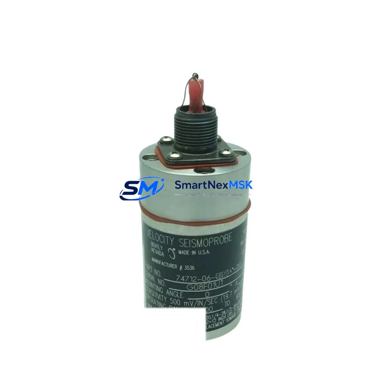
The Bently Nevada 74712-06-10-02-00 is a high-temperature proximity transducer engineered for the 3300 XL Series continuous vibration monitoring system. In rotating machinery protection applications — including steam turbines, gas compressors, centrifugal pumps, and large induction motors — this transducer serves as the primary sensing element for shaft radial vibration, axial position, and eccentricity measurement. When this component degrades or fails, the entire machinery protection loop is compromised, triggering unplanned shutdowns and exposing critical assets to catastrophic mechanical damage.
For maintenance engineers managing aging turbomachinery control cabinets, stocking a verified replacement of the 74712-06-10-02-00 is not optional — it is a fundamental element of any credible spare parts strategy. This listing provides an original-specification unit, fully tested prior to shipment, backed by a 12-month warranty, and available for rapid dispatch to minimize mean time to repair (MTTR).
Spare Maintenance Table
| Parameter | Specification |
|---|---|
| Part Number | 74712-06-10-02-00 |
| Brand | Bently Nevada |
| Series | 3300 XL |
| Product Type | High-Temperature Proximity Transducer |
| Measurement Function | Radial Vibration, Axial Position, Eccentricity |
| Cable Length | 10 ft (3.05 m) — per SKU suffix |
| Temperature Rating | High-temperature variant (suitable for elevated bearing housing environments) |
| Output Signal | -18 VDC nominal (standard 3300 XL system bias) |
| Compatibility | Bently Nevada 3300 XL Monitor System; 3300/16 and 3300/20 rack modules |
| Installation | Threaded tip, standard 3300 XL mounting bracket; gap set per OEM procedure |
| Application Environment | Turbomachinery bearing housings, compressor trains, pump bearing pedestals |
| Maintenance Recommendation | Replace at first sign of signal drift, gap instability, or cable jacket degradation |
| Origin | USA |
| Pre-Shipment Testing | Yes — functional and signal output verified |
| Warranty | 12 Months |
Maintenance Planning for Continuous Operation
When a maintenance or reliability engineer schedules replacement of the 74712-06-10-02-00 proximity transducer, the scope of inspection should extend well beyond the transducer itself. The 3300 XL measurement chain is a tightly coupled system, and a single degraded component can mask or misrepresent faults elsewhere in the loop.
Begin with the 3300 XL Extension Cable (typically the 330130 series), which connects the transducer to the proximitor/driver. Cable jacket cracking, connector corrosion, or shield continuity loss are common failure modes in high-temperature bearing environments and should be verified during any transducer swap. Immediately downstream, inspect the 3300 XL Proximitor/Oscillator-Demodulator (such as the 330180 or 330185 series) — the active driver that converts gap distance to a DC voltage signal. A worn or thermally stressed proximitor will produce erratic output even with a new transducer installed.
At the rack level, confirm the health of the 3300/16 Dual Vibration Monitor or 3300/20 Radial Vibration Monitor module seated in the 3300 rack. These modules process the transducer signal and generate relay trip outputs; internal relay contacts and A/D converter drift are known long-term failure modes. While the rack is open, inspect the 3300 Rack Power Supply module — an unstable or noisy DC rail will introduce measurement error across all channels simultaneously, a fault that is frequently misdiagnosed as a transducer problem.
For plants running integrated machinery protection and condition monitoring, verify the System 1 Evolution data acquisition interface or the legacy TDXnet communication module for firmware currency and communication integrity. Signal path integrity from transducer to historian is essential for trend-based predictive maintenance. Additionally, review the Keyphasor transducer (typically a 330980 or 330905 series) associated with the same shaft — Keyphasor signal quality directly affects phase and 1X/2X vector accuracy across all vibration channels on that machine train.
In the control cabinet, inspect terminal blocks and field wiring terminations for oxidation, loose screws, and insulation breakdown, particularly in high-vibration or high-humidity environments. Where signal isolation is required between the 3300 XL output and a DCS analog input card, verify the condition of any installed signal isolator or signal conditioner modules — degraded isolation can introduce ground loops that corrupt vibration readings. Finally, confirm that barrier or Zener barrier modules (if installed for hazardous area compliance) are within calibration and show no signs of thermal stress.
Site Replacement Workflow
Replacing the 74712-06-10-02-00 in a live plant environment requires a structured approach to avoid introducing new faults or extending downtime beyond the planned window.
Step 1 — Pre-Replacement Verification: Confirm the replacement unit’s part number matches the installed transducer exactly, including the cable length suffix (-10 = 10 ft) and temperature variant code (-02-00). Substituting a standard-temperature transducer in a high-temperature application will result in premature failure and potential false readings.
Step 2 — Gap Setting: Using a calibrated digital voltmeter, set the transducer gap to the OEM-specified voltage (typically -10.0 VDC ± 0.5 VDC for a 3300 XL system at nominal gap). Document the as-found and as-left gap values in the maintenance record.
Step 3 — Signal Verification: After installation, confirm that the monitor module displays a stable, noise-free signal within the OK band. Check for any alert or danger setpoint violations before returning the channel to service.
Step 4 — System Functional Test: Perform a channel functional test per the 3300 XL system documentation, verifying relay outputs, OK relay status, and communication to the DCS or historian. This step is critical before releasing the machine train to operations.
Step 5 — Documentation: Record the replaced part number, serial number (if available), installation date, gap setting, and technician sign-off in the plant CMMS. This data supports future predictive maintenance intervals and warranty claims.
This workflow applies equally to planned turnaround replacements and emergency breakdown scenarios. Having a pre-tested, in-stock 74712-06-10-02-00 unit eliminates the procurement lead time that typically accounts for 60–80% of total downtime duration in unplanned machinery protection failures.
Spare Parts Support FAQ
Q1: Is the 74712-06-10-02-00 a direct drop-in replacement for the original installed unit?
Yes. This unit is supplied to original Bently Nevada specifications for the 3300 XL series. It is compatible with all standard 3300 XL rack configurations, extension cables, and proximitor/driver modules. No firmware changes or system reconfiguration are required — only gap resetting per OEM procedure.
Q2: How is the unit tested before shipment?
Each 74712-06-10-02-00 unit undergoes functional verification including signal output check, cable continuity, and connector integrity inspection prior to dispatch. A test report is available upon request. This pre-shipment testing protocol ensures the unit is ready for immediate installation upon arrival at site.
Q3: What is the recommended spare parts stocking strategy for 3300 XL systems?
For critical machinery trains (turbines, compressors), we recommend maintaining a minimum of one transducer per monitored shaft position as an on-site cold spare, with a second unit held at the regional warehouse level. Extension cables and proximitor modules should be stocked at a ratio of one spare per four installed channels. This strategy aligns with ISA-18.2 and API 670 spare parts guidance for machinery protection systems.
Q4: What warranty coverage applies, and what does it include?
All units are covered by a 12-month warranty from the date of shipment. The warranty covers manufacturing defects, signal output non-conformance, and premature failure under normal operating conditions. Warranty claims are supported by our technical team at sales@smartnexmsk.com. Units damaged by incorrect installation, overvoltage, or mechanical impact are excluded from warranty coverage.
© 2026 SMARTNEXMSK. All rights reserved.
Original Source: https://smartnexmsk.com
Contact: sales@smartnexmsk.com | +86 18259474341


