Bently Nevada 81544-01 Retrofit-Ready Monitor for 3500 Series: Compatible Upgrade for Legacy Vibration Monitoring Systems
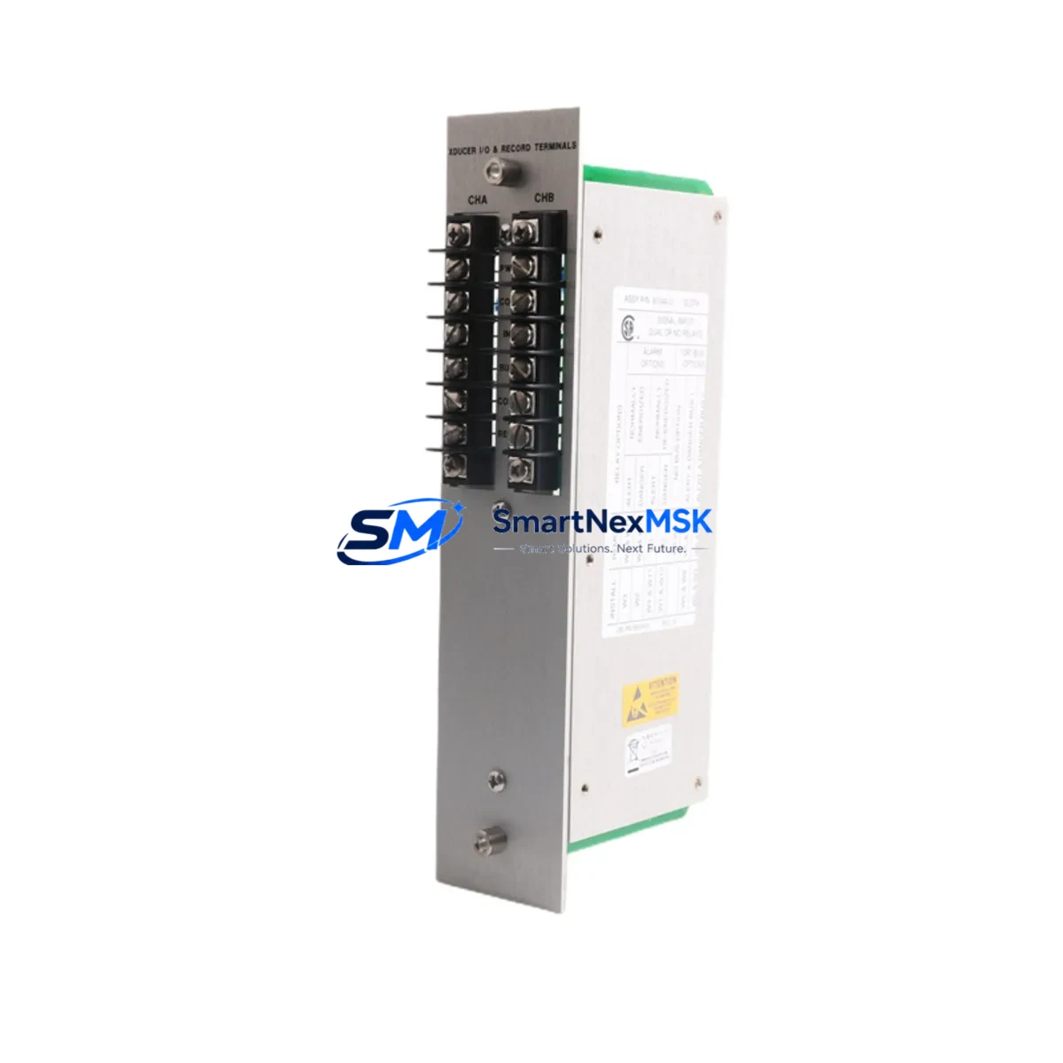
The Bently Nevada 81544-01 is a signal input and alarm output module engineered for the 3500 Series machinery protection platform. As original equipment manufacturers phase out legacy components and end-of-life notices become more common across the process industries, the 81544-01 has emerged as a critical retrofit solution for plants operating aging vibration monitoring infrastructure. Whether you are replacing a failed unit in an emergency shutdown scenario or executing a planned control system upgrade, this module provides a verified drop-in replacement path that preserves your existing rack architecture, wiring topology, and alarm logic without requiring a full system overhaul.
Industrial facilities running the Bently Nevada 3500 Series platform typically rely on a tightly integrated ecosystem of components. The 3500/15 Power Supply Module provides the regulated DC power backbone for the entire rack, and any replacement module must be confirmed compatible with the existing power budget before installation. Engineers should verify that the total current draw of all installed modules — including the 81544-01 and any co-installed 3500/22M Transient Data Interface or 3500/40M Proximitor Seismic Monitor modules — does not exceed the rated output of the power supply. This step is frequently overlooked during emergency replacements and can result in nuisance trips or intermittent faults after commissioning.
Upgrade Compatibility Table
| Parameter | Details |
|---|---|
| Compatible Platform | Bently Nevada 3500 Series Machinery Protection System |
| Module Function | Signal Input / Alarm Output (Vibration Monitoring) |
| Rack / Backplane Interface | 3500 Series standard backplane; confirm slot assignment with System 1 configuration file |
| Installation Requirement | Hot-swap capable; power-down recommended for first-time slot installation |
| Communication Compatibility | Modbus RTU / TCP, Ethernet (via 3500/92 Communication Gateway); verify firmware revision |
| Replacement Recommendation | Direct replacement for 81544-01; verify transducer wiring polarity and I/O terminal mapping before energizing |
| Commissioning Focus | Full-scale calibration check, alarm setpoint re-entry, OK relay verification, and System 1 database re-sync |
| Warranty | 12-Month Warranty — covers manufacturing defects and functional failure under normal operating conditions |
Retrofit Planning for Existing Automation Systems
A successful retrofit of the 81544-01 into an operating plant environment requires careful pre-engineering. Begin by pulling the existing System 1 configuration database and exporting the current alarm setpoints, full-scale ranges, and transducer scale factors for every channel associated with the module being replaced. These values must be re-entered manually after the new module is installed, as the 3500 Series does not automatically restore configuration from a replaced module. Failure to document this data before removal is one of the most common causes of extended downtime during unplanned replacements.
Terminal wiring on the 3500 Series uses a dedicated I/O terminal block that connects to the rear of the rack. Before removing the failed module, photograph or sketch the existing wiring layout, paying particular attention to the transducer power supply leads, the OK relay output terminals, and any 4–20 mA buffered output connections feeding the plant DCS. If the plant DCS is a Honeywell Experion PKS or an Emerson DeltaV system, the analog input cards receiving the buffered outputs will need to be verified for signal continuity after the replacement is complete.
For plants that have integrated the 3500 rack into a broader control architecture via the 3500/92 Communication Gateway, the Modbus register map must be confirmed against the SCADA or historian configuration. Any change in module slot position or firmware version can shift register addresses, causing data gaps in the process historian or false alarms in the control room. It is strongly recommended to perform a full Modbus poll test using a portable Modbus master tool before returning the system to automatic protection mode.
In multi-rack installations, the 3500/20 Rack Interface Module coordinates communication between the individual monitor modules and the plant network. Ensure that the rack interface firmware is compatible with the replacement 81544-01 module firmware. Mismatched firmware versions are a known source of intermittent communication faults that can be difficult to diagnose without access to the Bently Nevada System 1 diagnostic logs. Additionally, if the installation includes a 3500/05 System Rack or a 3500/10 System Rack, confirm that the backplane revision supports the module variant being installed.
For facilities upgrading from an older Bently Nevada 7200 Series or 3300 Series platform to the 3500 Series, the 81544-01 represents a significant step forward in diagnostic capability and network integration. The migration path typically involves replacing the legacy proximitor power supplies, re-terminating the Bently Nevada 330100 or 330130 proximity probes to the new terminal blocks, and updating the HMI faceplates in the control room to reflect the new alarm tag structure. Plants using a Wonderware InTouch or FactoryTalk View HMI will need to update the tag database and alarm summary displays to match the new module’s output format.
Downtime Control During System Migration
Minimizing unplanned downtime is the primary operational concern when replacing a vibration monitoring module in a running plant. The 81544-01 supports hot-swap insertion in most 3500 rack configurations, but the protection function for the associated machine train is interrupted from the moment the old module is removed until the new module completes its self-test and the alarm setpoints are restored. This window — typically 5 to 15 minutes for a prepared technician — represents the period of greatest risk, and plant management should be notified so that the machine can be placed under manual surveillance or taken offline if the process permits.
To reduce this exposure, prepare a commissioning checklist in advance that covers: power supply current budget verification, terminal wiring continuity check, module self-test pass confirmation, alarm setpoint re-entry from the documented configuration file, OK relay output verification, buffered output signal level check at the DCS input card, Modbus communication poll confirmation, and a final full-scale vibration simulation using a calibrated signal source. With this checklist in hand, a trained technician can complete the replacement and return the system to automatic protection in under 20 minutes, even in a first-time replacement scenario.
For planned maintenance windows, consider staging the replacement during a scheduled machine outage to eliminate the hot-swap risk entirely. Pre-configure the replacement 81544-01 on a bench using a 3500 Series test rack if available, load the configuration file, and verify all alarm outputs before bringing the module to the field. This approach reduces field commissioning time to under 5 minutes and virtually eliminates the risk of configuration errors under time pressure.
All units supplied are pre-tested prior to shipment, with functional verification performed under simulated operating conditions. In-stock inventory ensures same-day or next-day dispatch for urgent replacement requirements, supporting your downtime control objectives with reliable supply chain availability.
Retrofit Support FAQ
Q: Is the 81544-01 a direct drop-in replacement for the original Bently Nevada module of the same part number?
A: Yes. The 81544-01 is a form-fit-function replacement for the original Bently Nevada 81544-01. It installs into the same 3500 Series rack slot, uses the same terminal block wiring, and is compatible with the same System 1 configuration database. No mechanical modifications are required. Configuration re-entry is necessary after installation, as the module does not retain the previous unit’s settings.
Q: What commissioning steps are required after installing the replacement module?
A: After physical installation, the technician must re-enter all alarm setpoints, full-scale ranges, and transducer scale factors using the System 1 software. The OK relay output should be verified under both normal and alarm conditions. If the module is connected to a plant DCS or historian via the 3500/92 Communication Gateway, a Modbus poll test should be performed to confirm register mapping integrity. A final vibration simulation using a calibrated signal source is recommended before returning the system to automatic protection.
Q: How do I verify wiring compatibility before removing the failed module?
A: Document the existing terminal wiring layout before removal, including transducer power supply leads, OK relay output terminals, and any buffered analog output connections. Compare the terminal assignment against the 3500 Series wiring diagram for the 81544-01. Pay particular attention to transducer wiring polarity, as reversed polarity will cause the module to report a transducer fault immediately upon energization. If the original wiring documentation is unavailable, a continuity check from the terminal block to the field junction box will confirm the existing circuit topology.
Q: What does the 12-month warranty cover, and what is the return process?
A: The 12-month warranty covers manufacturing defects and functional failure under normal operating conditions from the date of shipment. It does not cover damage resulting from incorrect installation, overvoltage, or physical impact. To initiate a warranty claim, contact our technical support team with the order reference number and a description of the observed fault. A replacement unit will be dispatched upon confirmation of the defect, and the failed unit should be returned in its original packaging for inspection.
© 2026 SMARTNEXMSK. All rights reserved.
Original Source: https://smartnexmsk.com
Contact: sales@smartnexmsk.com | +86 18259474341


