Bently Nevada 81546-01 Spare for 3500 Series Automation: Spare Replacement & Industrial Downtime Risk Control
The Bently Nevada 81546-01 is a Relay Output Module designed for the 3500 Series Machinery Protection System (MPS) — one of the most widely deployed vibration monitoring and machinery protection platforms in rotating equipment environments worldwide. Whether you are managing a planned turnaround, responding to an unplanned trip, or building a proactive spare parts inventory for a critical compressor train or turbine skid, the 81546-01 is a high-priority line item on any maintenance engineer’s BOM.
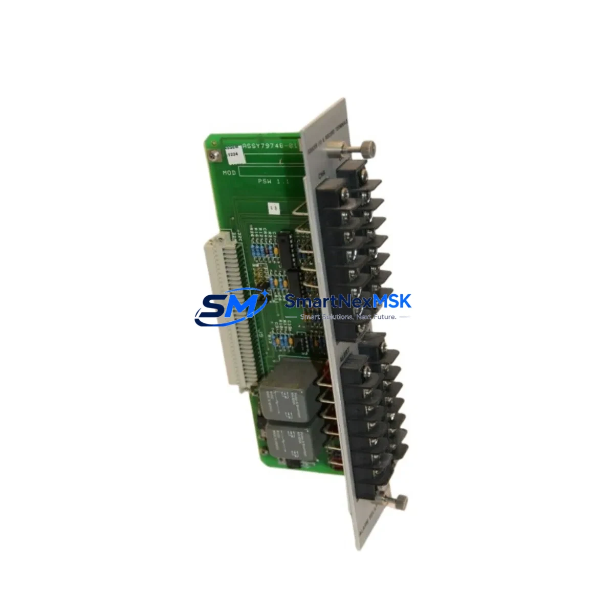
This module provides relay contact outputs that interface directly with the 3500 rack’s alarm and shutdown logic. When a relay output module fails or degrades, the entire protection loop is compromised — potentially masking dangerous vibration events or triggering nuisance trips. Fast, verified replacement with an original-specification spare is the only acceptable recovery path in safety-critical applications.
At SMARTNEXMSK, every 81546-01 unit is sourced from verified supply channels, inspected prior to dispatch, and shipped with a 12-month warranty. We maintain ready stock to support emergency same-day quotation and rapid international logistics to minimize your system downtime window.
Spare Maintenance Table
| Parameter | Specification / Detail |
|---|---|
| Part Number | 81546-01 |
| Brand | Bently Nevada |
| Series | 3500 Machinery Protection System |
| Module Type | Relay Output Module |
| Output Type | Relay contact outputs (alarm / shutdown) |
| Rack Compatibility | 3500/32, 3500/42, 3500/44, 3500/45, 3500/50, 3500/60, 3500/72M racks |
| Installation | Plug-in module, rear-panel I/O termination |
| Operating Environment | Industrial — turbines, compressors, pumps, fans, gearboxes |
| Origin | USA |
| Maintenance Recommendation | Replace at first sign of relay chatter, contact resistance drift, or failed self-test; inspect every planned shutdown |
| Warranty | 12 Months |
| Pre-shipment Test | Function-verified before dispatch |
| Lead Time | In-stock; same-day quotation available |
Maintenance Planning for Continuous Operation
Replacing the 81546-01 Relay Output Module is rarely an isolated task. In a 3500 Series rack, the relay output module works in concert with multiple upstream and downstream components, and a thorough maintenance engineer will use any relay module replacement as an opportunity to audit the entire protection loop.
Begin with the 3500/20 Power Supply Module — relay coil chatter and intermittent contact failures are frequently caused by power supply ripple or voltage sag rather than a faulty relay module itself. Confirm DC rail stability before condemning the 81546-01. Similarly, inspect the 3500/15 Power Supply (redundant supply slot) if your rack is configured for dual-supply redundancy.
Upstream of the relay module, verify the monitor card driving the relay logic. Common companions in a compressor protection rack include the 3500/42M Proximitor / Seismic Monitor for radial vibration, the 3500/45 Position Monitor for axial thrust, and the 3500/50M Tachometer Module for speed and phase reference. If any of these monitors are showing intermittent OK/Not-OK transitions, the relay output module may be responding correctly to a genuine upstream fault — not failing independently.
Check the 3500/32 4-Channel Relay Module if your rack uses dedicated relay expansion slots; in some configurations, the 81546-01 and the 3500/32 share the same alarm bus, and a fault in one can mask or simulate a fault in the other. Inspect all relay wiring terminations at the rear I/O module — corroded terminals, loose ferrules, and undersized wire gauge are common causes of relay output degradation in high-vibration environments.
For racks integrated with a DCS or safety system, also inspect the 3500/92 Communication Gateway Module or 3500/93 Communication Module to confirm that relay status is being correctly reported to the control room. A relay module replacement that is not followed by a communication gateway function check can leave operators with stale or incorrect trip status on their HMI screens.
Finally, review the condition of the 3500 Rack Backplane and connector pins. Relay modules that have been inserted and removed multiple times in emergency scenarios can cause pin wear that leads to intermittent contact — a problem that will recur regardless of how many relay modules are replaced if the backplane is not addressed.
Building a minimum viable spare parts kit around the 81546-01 for a single 3500 rack should include at least one spare power supply module, one spare relay output module, and one spare monitor card for each critical measurement type in the rack. This kit approach is standard practice in petrochemical, power generation, and offshore platforms where 3500 Series systems protect API 670-compliant machinery.
Site Replacement Workflow
Step 1 — Verify compatibility before removal. Confirm the replacement 81546-01 matches the existing module’s firmware revision and jumper configuration. Bently Nevada relay output modules may have application-specific jumper settings for normally energized vs. normally de-energized relay logic. Document the existing configuration before pulling the module.
Step 2 — Coordinate with operations. Relay output modules in a live protection rack cannot be hot-swapped without bypassing the associated alarm and shutdown channels. Follow your site’s Management of Change (MOC) and bypass authorization procedure. Notify the control room before initiating any bypass.
Step 3 — Remove and inspect. Extract the 81546-01 carefully using the module ejector levers. Inspect the rear connector for pin damage, corrosion, or debris. Clean the backplane connector with approved contact cleaner if contamination is present.
Step 4 — Install the replacement module. Seat the new 81546-01 firmly until the front panel latch engages. Restore power and observe the module’s OK LED. Allow the 3500 rack to complete its self-test sequence before removing any bypasses.
Step 5 — Functional verification. Use the Bently Nevada System 1 software or the rack’s front-panel interface to confirm relay contact status, alarm setpoint response, and OK relay state. Perform a loop test to verify that relay contacts are correctly wired to the downstream shutdown device or DCS input card.
Step 6 — Remove bypass and return to service. Remove all channel bypasses in reverse order of application. Confirm with the control room that all alarm and shutdown indications are normal before signing off the work order.
This workflow applies equally to planned turnaround replacements and emergency unplanned replacements. The key difference in an emergency scenario is pre-positioning a verified spare — which is exactly the supply capability SMARTNEXMSK provides.
Spare Parts Support FAQ
Q1: Is the 81546-01 still available as a new original spare, or only as a refurbished unit?
The 81546-01 is available from SMARTNEXMSK as a verified original spare. Units are sourced from authorized distribution channels and inspected prior to shipment. Each unit is function-tested and ships with a 12-month warranty covering manufacturing defects and functional failure under normal operating conditions.
Q2: How do I confirm compatibility with my existing 3500 rack configuration before ordering?
Provide your rack model number, slot assignment, and existing module firmware revision when requesting a quotation. Our technical team will cross-reference your configuration against the Bently Nevada 3500 Series compatibility matrix and confirm fit before shipment. We also recommend reviewing the 3500 Relay Output Module Installation Manual (document 129768-01) for jumper configuration details specific to your application.
Q3: What is the recommended spare parts stocking strategy for a 3500 Series rack?
For a single critical 3500 rack protecting a compressor or turbine, the industry-standard approach is to stock one spare for each unique module type installed. For multi-rack installations, a shared pool of two to three relay output modules per site is typical. Modules should be stored in anti-static packaging in a climate-controlled environment and rotated into service on a first-in, first-out basis to prevent long-term storage degradation of relay contacts.
Q4: What does the 12-month warranty cover, and what is the return process if a unit fails?
The 12-month warranty covers functional failure under normal operating conditions, including relay contact failure, module self-test failure, and OK LED fault. Physical damage caused by incorrect installation, overvoltage, or environmental contamination is excluded. To initiate a warranty claim, contact sales@smartnexmsk.com with your order number, site details, and a description of the failure mode. We will arrange return logistics and dispatch a replacement unit to minimize your downtime.
© 2026 SMARTNEXMSK. All rights reserved.
Original Source: https://smartnexmsk.com
Contact: sales@smartnexmsk.com | +86 18259474341


