Bently Nevada 84145-01 Retrofit-Ready Seismic Relay for 3500 Series Control Systems
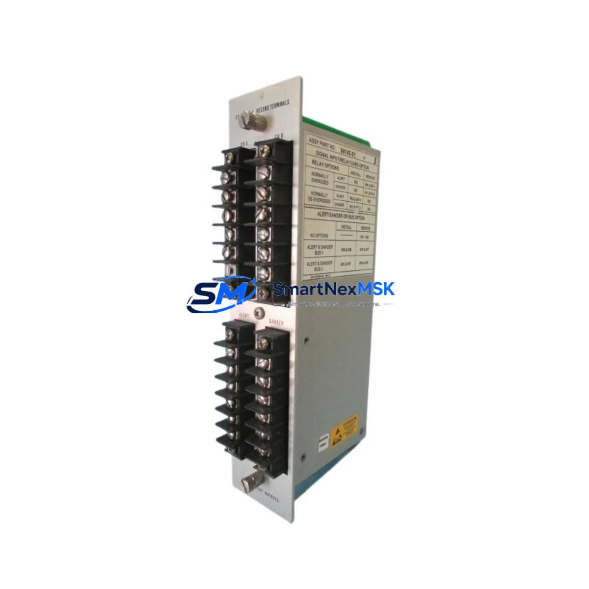
The Bently Nevada 84145-01 is a Seismic Dual Epoxy Relay Module engineered for the 3500 Series Machinery Protection System. As legacy 3500 Series installations age and original spare parts become increasingly difficult to source, the 84145-01 serves as a verified retrofit-ready replacement that preserves existing wiring configurations, backplane interface assignments, and relay output logic — enabling plant engineers to restore system integrity without redesigning the control architecture.
This module is stocked and tested at our Xiamen facility, ships with a 12-month warranty, and is supported by pre-shipment functional verification. Whether you are replacing a failed relay in an active machinery protection rack or building a critical spare inventory ahead of a planned shutdown, the 84145-01 delivers the compatibility and reliability that industrial maintenance teams require.
Upgrade Compatibility Table
| Parameter | Details |
|---|---|
| Compatible Platform | Bently Nevada 3500 Series Machinery Protection System |
| Module Type | Seismic Dual Epoxy Relay Output Module |
| Backplane Interface | Standard 3500 Series rack backplane — no adapter required |
| Wiring Compatibility | Direct terminal-for-terminal replacement; existing field wiring retained |
| Relay Output | Dual relay, epoxy-sealed contacts for vibration alarm and trip logic |
| Communication | Integrated via 3500 rack communication bus; no protocol reconfiguration required |
| Module Address | Slot-based addressing inherited from rack position; verify in System 1 or Rack Configuration Utility |
| Installation Requirement | Power down rack before insertion; re-enable relay outputs after seating |
| Replacement Recommendation | Direct drop-in for failed or end-of-life 84145-01 units in 3500/20, 3500/22, 3500/32, 3500/40 racks |
| Commissioning Note | Verify relay setpoints in Rack Configuration Utility after installation; confirm OK relay state before restart |
| Warranty | 12 months from date of shipment; covers manufacturing defects and functional failure |
Retrofit Planning for Existing Automation Systems
Integrating the 84145-01 into an existing 3500 Series rack requires a structured approach that accounts for the full scope of the machinery protection architecture. In a typical retrofit scenario, the 3500 rack may house a combination of modules including the 3500/20 Rack Interface Module, 3500/22 Transient Data Interface, 3500/32 4-Channel Relay Module, and 3500/40 Proximitor/Seismic Monitor. Each of these modules shares the rack backplane and communicates through the integrated bus — meaning a relay module swap must be coordinated with the monitor module configuration to ensure alarm and trip relay assignments remain consistent.
Before removing the failed 84145-01, engineers should document the current relay output assignments using the Bently Nevada Rack Configuration Utility (RCU) or System 1 Condition Monitoring Software. Relay channel mapping, OK relay polarity, and voted trip logic (1oo2, 2oo3) must be recorded and verified against the replacement module after installation. If the rack is connected to a DCS or Safety Instrumented System (SIS) via hardwired relay contacts, the field terminal block wiring on the 3500/20 I/O Module should be photographed and labeled before disconnection.
Power supply integrity is a critical pre-check. The 3500/15 Power Supply Module must be verified to deliver stable DC voltage within specification before inserting the replacement relay module. An undersized or aging power supply can cause intermittent relay chatter or false trip events after module replacement. If the rack uses a redundant power supply configuration, both supplies should be load-tested before the retrofit window begins.
For plants migrating from older 7200 Series or 3300 Series Bently Nevada systems to the 3500 platform, the 84145-01 relay module is a key component in the upgraded rack assembly. The migration typically involves replacing the legacy 3300/16 Dual Voting Trip Module or 7200/60 Relay Module with the 3500 Series relay architecture, which requires re-terminating field wiring to the new I/O terminal blocks and updating the relay logic in the configuration software. The 3500/92 Communication Gateway Module may also need to be added if the upgraded rack is to be integrated with a Modbus TCP or OPC DA/UA data highway for DCS connectivity.
HMI screens connected to the machinery protection system — whether running on a Wonderware InTouch, FactoryTalk View, or Ignition SCADA platform — should be reviewed to confirm that relay status tags, alarm acknowledgment logic, and trip bypass indicators are correctly mapped to the new module’s relay outputs. Tag database updates may be required if the module slot position changes during the retrofit.
Downtime Control During System Migration
Minimizing unplanned downtime during a relay module replacement on a live machinery protection rack requires careful pre-staging and a defined bypass procedure. Before the maintenance window opens, the replacement 84145-01 should be bench-tested using a portable relay test set to verify contact continuity, coil resistance, and OK relay state. This eliminates the risk of installing a module that fails immediately upon power-up.
During the swap, the affected machinery should be placed in a controlled shutdown state or the relay outputs should be bypassed at the DCS or SIS level using an approved bypass key switch or software inhibit. The bypass must be logged in the plant’s Management of Change (MOC) system and time-limited to the duration of the maintenance activity. The original program logic stored in the rack — including setpoint values, time delays, and voted trip configurations — is retained in the 3500/20 Rack Interface Module non-volatile memory and is not lost during a relay module hot-swap in racks that support it.
After the 84145-01 is seated and the rack is re-energized, the commissioning sequence should include: confirming the OK relay energizes within the expected time window, verifying alarm relay setpoints against the process historian baseline, performing a relay output function test by simulating an over-vibration condition using the rack’s built-in test function, and confirming that the DCS or SIS receives the correct hardwired trip signal. Full commissioning records should be retained for audit and insurance compliance purposes.
Retrofit Support FAQ
Q1: Is the 84145-01 a direct drop-in replacement for the original Bently Nevada unit?
Yes. The 84145-01 is a form-fit-function replacement for the original Bently Nevada Seismic Dual Epoxy Relay Module used in 3500 Series racks. No wiring changes, backplane adapters, or configuration file modifications are required for a like-for-like swap. Relay setpoints and output assignments are stored in the rack interface module and are automatically applied to the replacement unit upon power-up.
Q2: What commissioning steps are required after installation?
After seating the module and restoring rack power, use the Rack Configuration Utility to confirm the relay module is recognized in its assigned slot. Verify OK relay status, check alarm and trip relay setpoint values, and perform a functional relay output test. If the rack is connected to a DCS or SIS, confirm hardwired relay contact signals are received correctly at the remote I/O or safety logic solver. Document all commissioning results before removing the bypass.
Q3: How is wiring compatibility confirmed before ordering?
The 84145-01 uses the standard 3500 Series relay module terminal block pinout. Confirm your existing field wiring connects to a 3500/20 or compatible I/O module terminal block. If your rack uses an older wiring harness from a 3300 or 7200 Series migration, a terminal adapter or re-termination to the 3500 I/O block will be required. Our technical team can review your rack drawing and wiring diagram before shipment to confirm compatibility.
Q4: What does the 12-month warranty cover?
All 84145-01 units ship with a 12-month warranty covering manufacturing defects, relay contact failure, and functional non-conformance under normal operating conditions. Each unit undergoes pre-shipment functional testing including relay coil energization, contact resistance measurement, and OK relay state verification. Warranty claims are supported by our Xiamen technical team with replacement dispatch within 5 business days of confirmed fault diagnosis.
© 2026 SMARTNEXMSK. All rights reserved.
Original Source: https://smartnexmsk.com
Contact: sales@smartnexmsk.com | +86 18259474341


