Bently Nevada 84661-10 Retrofit-Ready Interconnect Cable for 3500 Series Control Systems
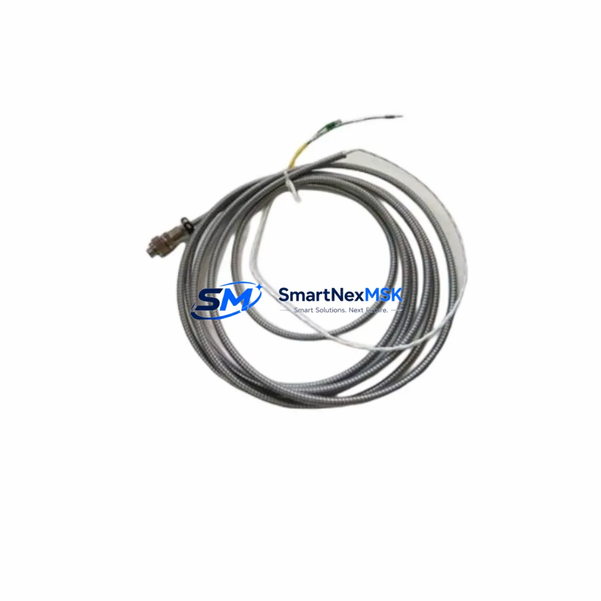
The Bently Nevada 84661-10 is a precision-engineered interconnect cable designed for seamless integration within the Bently Nevada 3500 Series machinery protection and condition monitoring platform. As legacy vibration monitoring systems approach end-of-life or require component-level replacement, the 84661-10 serves as a critical link between transducer inputs and the 3500 rack-mounted monitoring modules — enabling plant engineers to restore full system functionality without replacing the entire monitoring architecture.
Whether you are replacing a failed cable on an operating turbine protection loop, upgrading a brownfield compressor monitoring system, or restoring a mothballed 3500/22M Transient Data Interface rack, the 84661-10 provides the correct pinout, shielding specification, and connector geometry to maintain signal integrity across the full measurement chain. This cable is compatible with the 3500/40M Proximitor/Seismic Monitor, 3500/42M Proximitor/Seismic Monitor, and 3500/45 Position Monitor modules, making it a versatile retrofit component across multiple card slot configurations within the same chassis.
Upgrade Compatibility Table
| Parameter | Details |
|---|---|
| SKU / Part Number | 84661-10 |
| Brand | Bently Nevada |
| Compatible Platform | Bently Nevada 3500 Series Machinery Protection System |
| Compatible Modules | 3500/40M, 3500/42M, 3500/45, 3500/22M, 3500/15 Power Supply |
| Connector Interface | Standard 3500 Series rack I/O terminal block interface |
| Installation Requirement | No rack modification required; direct plug-in replacement |
| Communication Compatibility | Compatible with 3500/20 Rack Interface Module (RIM) and System 1 software integration |
| Replacement Recommendation | Direct drop-in replacement for worn, damaged, or discontinued 84661-10 cables |
| Commissioning Notes | Verify transducer gap voltage and OK relay status after cable swap; re-run channel OK check in System 1 |
| Warranty | 12-Month Warranty — covers manufacturing defects and signal integrity failures |
Retrofit Planning for Existing Automation Systems
Successful retrofit of the 84661-10 within an active 3500 Series rack requires a structured approach to component verification and sequencing. Before initiating the cable swap, engineers should confirm the health status of adjacent modules within the same chassis. The 3500/15 Power Supply module should be checked for output voltage stability — an undersized or aging power supply can introduce noise artifacts that mimic cable faults. Similarly, the 3500/20 Rack Interface Module (RIM) should be confirmed as communicating correctly with the host DCS or System 1 condition monitoring software before and after the cable replacement to isolate the fault to the cable itself.
For plants running Proximitor sensors such as the 3300 XL 8mm Proximitor or the 330180 Proximitor, the interconnect cable is the signal path between the sensor and the 3500/40M or 3500/42M monitor card. Any degradation in cable shielding or connector contact resistance will directly affect the gap voltage reading and the vibration amplitude accuracy. When replacing the 84661-10, technicians should also inspect the 330130-080-00-05 extension cable and the field-side junction box terminals for corrosion or mechanical damage.
In control cabinet upgrades where the 3500 rack is being relocated or the cabinet layout is being redesigned, the cable routing path must be re-evaluated. The 84661-10 should be routed away from high-voltage power conductors and VFD output cables to prevent electromagnetic interference. If the retrofit involves migrating from an older 3300 Series monitoring system to the 3500 platform, the I/O terminal mapping will differ and a full re-termination of field wiring at the 3500 I/O module terminal blocks will be required. In such cases, the 3500/92 Communication Gateway may also need to be reconfigured to reflect the new channel assignments and alarm setpoints.
For plants integrating the 3500 system with a Modbus or FOUNDATION Fieldbus DCS backbone, the 3500/92 Communication Gateway handles protocol translation and should be verified for firmware compatibility with the host system after any hardware change. If the retrofit also involves adding new measurement channels — for example, expanding from radial vibration monitoring to include axial position measurement — additional 3500/45 Position Monitor modules and their associated cables will need to be sourced and installed in available rack slots.
Downtime Control During System Migration
Minimizing unplanned downtime during a 3500 Series cable replacement requires pre-staging all replacement components and completing as much pre-work as possible during scheduled maintenance windows. The 84661-10 cable swap itself is a low-risk, non-invasive procedure — the 3500 rack does not need to be powered down if the affected channel can be bypassed at the 3500/20 RIM and the associated machine protection logic is temporarily inhibited at the DCS level. However, plant safety procedures must be followed, and the bypass must be formally authorized and time-limited.
Before removing the existing cable, technicians should document the current gap voltage, direct vibration, and 1X/2X amplitude readings from the System 1 historian or the local 3500/94 Display Interface Module. These baseline values serve as the acceptance criteria for post-replacement commissioning. After installing the 84661-10, the channel should be re-enabled and the live readings compared against the documented baseline. A deviation of more than ±0.5 VDC in gap voltage or more than ±5% in vibration amplitude should trigger further investigation before the bypass is removed and the protection logic is re-armed.
For multi-channel retrofits or full rack replacements, a phased approach is recommended — replacing one cable or one module at a time, verifying each channel before proceeding to the next. This approach preserves the integrity of the overall protection system and ensures that the machine remains protected throughout the migration process. All configuration changes, alarm setpoint adjustments, and OK relay status checks should be logged in the plant maintenance management system for traceability and audit compliance.
Retrofit Support FAQ
Q1: Is the 84661-10 a direct replacement for the original Bently Nevada cable, or are there wiring differences I need to account for?
The 84661-10 is a direct drop-in replacement with identical pinout and connector geometry to the original factory cable. No re-termination of field wiring is required. However, we recommend verifying the connector seating and locking mechanism after installation, as worn rack connectors on older 3500 chassis may require cleaning before achieving a reliable connection.
Q2: Will replacing the 84661-10 affect my existing System 1 configuration or alarm setpoints?
No. The cable replacement is transparent to the System 1 software and the 3500/20 RIM configuration. Alarm setpoints, channel scaling, and OK relay thresholds are stored in the monitor module firmware and are not affected by a cable swap. A channel OK check and gap voltage verification are the only commissioning steps required after replacement.
Q3: What is included in the 12-month warranty, and what does the pre-shipment testing cover?
Every 84661-10 unit is tested for continuity, insulation resistance, and connector integrity before shipment. The 12-month warranty covers manufacturing defects, connector failure, and signal integrity issues under normal operating conditions. Warranty claims are supported with replacement or full refund. Contact sales@smartnexmsk.com for RMA procedures.
Q4: Can this cable be used in hazardous area (Ex) installations?
The 84661-10 is designed for use within the 3500 Series rack enclosure and the associated field wiring runs in standard industrial environments. For installations in classified hazardous areas (Zone 1/2 or Division 1/2), the overall system design — including cable routing, junction boxes, and Zener barriers or galvanic isolators — must comply with the applicable area classification standard. Consult your plant electrical engineer and the Bently Nevada 3500 Series installation manual for Ex-specific wiring requirements.
© 2026 SMARTNEXMSK. All rights reserved.
Original Source: https://smartnexmsk.com
Contact: sales@smartnexmsk.com | +86 18259474341


