Bently Nevada 86517-01-01-01-02 Retrofit-Ready Acceleration Interface for 3500 Series Control Systems
The Bently Nevada 86517-01-01-01-02 is a precision-engineered Acceleration Interface Module designed for seamless integration into the Bently Nevada 3500 Series machinery protection and condition monitoring platform. As legacy vibration monitoring systems reach end-of-life or face discontinued spare parts availability, the 86517-01-01-01-02 serves as a verified drop-in replacement and retrofit-ready upgrade path for facilities operating aging 3500 rack-based architectures. Whether you are managing a planned outage, responding to an unplanned module failure, or executing a phased control system modernization, this module delivers the signal conditioning, channel isolation, and transducer compatibility required to restore full system integrity with minimal engineering rework.
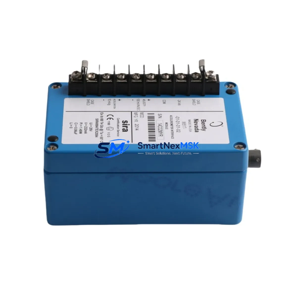
The 86517-01-01-01-02 accepts input from standard industrial accelerometers and velocity transducers, converting raw vibration signals into conditioned outputs compatible with the 3500/42M Proximitor/Seismic Monitor and adjacent I/O modules within the same rack. Its terminal block wiring layout is consistent with earlier 3500 Series acceleration interface variants, allowing field technicians to reuse existing cable runs and terminal assignments in most retrofit scenarios. Before installation, engineers should verify the transducer supply voltage, confirm the OK relay output wiring, and cross-reference the module address setting against the existing rack configuration stored in the 3500 Rack Configuration Software (RCS).
When replacing a failed or obsolete acceleration interface in an active 3500 rack, the recommended procedure begins with a controlled shutdown of the affected monitoring channel, followed by documentation of the existing terminal wiring using the original loop drawings. The 3500/01 Rack Interface Module and 3500/05 Power Supply Module should remain energized where possible to preserve communication continuity with the plant DCS or safety system. After physical module swap, the replacement 86517-01-01-01-02 must be configured using the same RCS project file, with particular attention to full-scale range, transducer type, and alert/danger setpoints previously validated during commissioning. If the plant historian or DCS — such as a Honeywell Experion PKS or Emerson DeltaV system — is receiving vibration data via Modbus or OPC-DA from the 3500 rack, the communication link should be verified post-swap before returning the machine to service.
Upgrade Compatibility Table
| Parameter | Details |
|---|---|
| Compatible Platform | Bently Nevada 3500 Series Machinery Protection System |
| Module Function | Acceleration Interface (Seismic / Vibration Signal Conditioning) |
| Transducer Compatibility | Standard industrial accelerometers and velocity transducers |
| Rack Interface | 3500 Series backplane — compatible with 3500/01 Rack Interface Module |
| Power Supply Requirement | Supplied via 3500/05 or 3500/15 Power Supply Module in rack |
| Terminal Wiring | Removable terminal block; reuse of existing field wiring supported in most cases |
| Communication Compatibility | Modbus RTU / TCP, OPC-DA via 3500 Rack Interface Module |
| Configuration Tool | Bently Nevada 3500 Rack Configuration Software (RCS) |
| Replacement Recommendation | Direct replacement for discontinued 3500 Series acceleration interface variants |
| Commissioning Note | Verify channel address, setpoints, and transducer type in RCS before restart |
| Warranty | 12-Month Warranty — covers manufacturing defects and functional failure |
Retrofit Planning for Existing Automation Systems
Successful retrofit of the 86517-01-01-01-02 into an operating plant environment requires a structured approach that accounts for both the physical installation and the broader control system context. In a typical 3500 rack assembly, the acceleration interface module occupies a dedicated slot adjacent to the 3500/42M Proximitor/Seismic Monitor, which handles proximity probe inputs for shaft vibration measurement. Facilities that monitor both radial vibration and axial position on the same machine train will often have the 86517-01-01-01-02 installed alongside a 3500/40M Proximitor Monitor, sharing the same rack backplane and power distribution from the 3500/05 Power Supply Module.
For plants executing a broader migration from the legacy 3500 platform toward the System 1 condition monitoring software environment, the 86517-01-01-01-02 remains fully compatible with the System 1 data acquisition layer, provided the 3500/01 Rack Interface Module firmware is at a supported revision. Engineers should confirm the firmware version of the rack interface module and cross-check against the System 1 compatibility matrix before committing to a phased upgrade schedule. In parallel, the 3500/22M Transient Data Interface Module — if installed in the same rack — should be verified for channel mapping consistency, as transient capture configurations reference acceleration channel assignments that must remain stable across the module swap.
Facilities that have standardized on Profibus DP or FOUNDATION Fieldbus for their process instrumentation layer should note that the 3500 Series communicates via its own proprietary backplane and Modbus/OPC gateway rather than native fieldbus protocols. If the retrofit is part of a broader protocol migration toward HART or EtherNet/IP, a gateway device such as the 3500/92 Communication Gateway Module may be required to bridge the 3500 rack data to the plant network. The 3500/20 Rack Configuration Module and associated programming cable (typically a standard RS-232 or USB-to-serial adapter) are required for any configuration changes made during the retrofit window. Spare 3500 Series I/O terminal blocks and connector kits should be staged in advance to avoid delays during the maintenance window.
Downtime Control During System Migration
Minimizing unplanned downtime during a 3500 Series module replacement requires pre-staging the replacement 86517-01-01-01-02, completing all configuration work offline using a backup RCS project file, and coordinating the physical swap with the operations team to align with a scheduled maintenance window or a controlled machine coast-down. Where the plant safety system — such as a Triconex or Yokogawa ProSafe-RS SIL-rated controller — receives a hardwired trip signal from the 3500 rack, the safety interlock logic should be placed in bypass mode through the approved management-of-change procedure before the module is removed, and the bypass must be lifted and verified immediately after the replacement module is confirmed healthy.
To protect the original program logic and setpoint database, a full RCS project export should be performed before any hardware change and stored on a secure engineering workstation. After the 86517-01-01-01-02 is installed and configured, a channel-by-channel functional verification should be conducted using a portable vibration calibrator to inject a known signal at the transducer input terminals and confirm that the module outputs the correct overall vibration level, alert, and danger relay states. This pre-return-to-service test, combined with a review of the DCS historian trend for the affected channels, provides the documentation required for post-maintenance sign-off and supports the 12-month warranty claim process if any functional issue is identified after restart.
Retrofit Support FAQ
Q: Is the 86517-01-01-01-02 a direct replacement for earlier Bently Nevada 3500 Series acceleration interface modules?
A: In most cases, yes. The 86517-01-01-01-02 is designed as a retrofit-compatible replacement for discontinued acceleration interface variants within the 3500 Series platform. Terminal wiring layouts and rack backplane interfaces are consistent with earlier module generations. We recommend verifying the RCS configuration file and transducer type before installation to confirm full compatibility with your specific rack revision.
Q: What wiring checks are required before installing the replacement module?
A: Before removing the failed module, photograph or document all terminal block wiring using the original loop drawings. Verify transducer supply voltage at the field terminals, confirm shield grounding continuity, and check that the OK relay output wiring matches the replacement module’s terminal assignment. The removable terminal block design of the 3500 Series simplifies this process, but field verification is always recommended.
Q: How is the replacement module configured after installation?
A: The 86517-01-01-01-02 is configured using the Bently Nevada 3500 Rack Configuration Software (RCS). Load the existing project backup file, assign the correct slot address, verify transducer type, full-scale range, and alert/danger setpoints, then download the configuration to the rack. A functional test using a portable calibrator is recommended before returning the machine to service.
Q: What does the 12-month warranty cover?
A: The 12-month warranty covers manufacturing defects and functional failure under normal operating conditions. Each unit undergoes pre-shipment functional testing to verify signal conditioning performance and relay output operation. Warranty claims are supported with documentation of the installation configuration and test results. Contact sales@smartnexmsk.com for warranty service inquiries.
© 2026 SMARTNEXMSK. All rights reserved.
Original Source: https://smartnexmsk.com
Contact: sales@smartnexmsk.com | +86 18259474341


