Bently Nevada 89477-10 Retrofit-Ready Piezo-Velocity Sensor for 3500 Series Control Systems
The Bently Nevada 89477-10 Velomitor Piezo-Velocity Sensor is a precision vibration measurement device engineered for continuous machinery monitoring in critical industrial environments. As legacy installations age and OEM support windows close, the 89477-10 has become one of the most sought-after retrofit and replacement components for facilities operating Bently Nevada 3500 Series Condition Monitoring Systems (CMS). Whether you are replacing a failed unit on a running production line, upgrading an aging vibration monitoring cabinet, or migrating from an earlier 7200 Series or 3300 Series platform, the 89477-10 delivers the electrical and mechanical compatibility required for a smooth, low-risk transition.
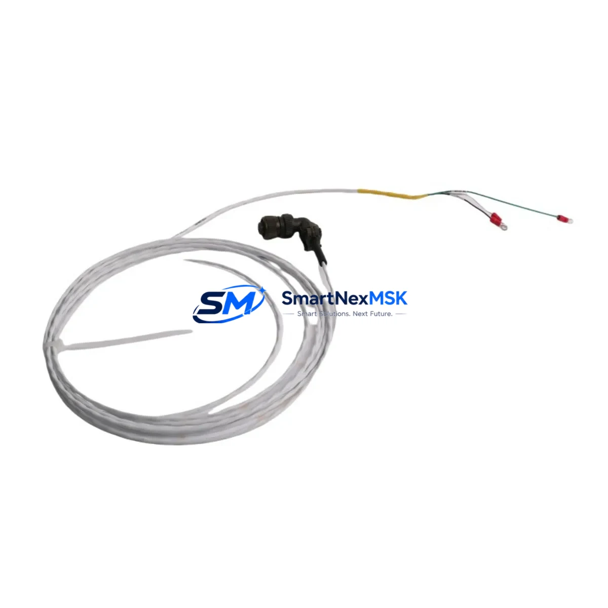
This sensor outputs a velocity signal in mV/mm/s (or mV/in/s), making it directly interchangeable with existing Velomitor-compatible input cards in the 3500/42M Proximitor/Seismic Monitor module and the 3500/40M Proximitor Monitor. Engineers performing a panel-level upgrade will find that the 89477-10 integrates without modification to existing Bently Nevada TK-3 junction boxes or field wiring, provided cable shielding and grounding practices conform to the original installation standard. The sensor’s integral 2-pin MIL-C-5015 connector mates directly with standard Velomitor extension cables, eliminating the need for field-fabricated adapters during a time-critical swap.
Upgrade Compatibility Table
| Parameter | Detail |
|---|---|
| SKU / Part Number | 89477-10 |
| Brand / OEM | Bently Nevada (Baker Hughes) |
| Series Compatibility | 3500 Series CMS (3500/42M, 3500/40M); compatible with legacy 3300 Series wiring infrastructure |
| Sensor Type | Piezo-Velocity (Velomitor) |
| Output Signal | Velocity (mV/mm/s or mV/in/s) |
| Connector Interface | 2-pin MIL-C-5015 integral connector |
| Mounting | Stud-mount (10-32 UNF or M6 adapter available) |
| Cable Compatibility | Standard Velomitor extension cables; TK-3 junction box compatible |
| Communication Protocol | Analog 4–20 mA / voltage output; compatible with 3500 rack Modbus RTU and System 1 software |
| Replacement For | Bently Nevada 89477-01, 89477-02 (earlier Velomitor variants); 3300/16 seismic sensor legacy installations |
| Commissioning Note | Verify rack channel sensitivity scaling in 3500 Rack Configuration Software before live restart |
| Warranty | 12 Months — covers manufacturing defects and electrical performance |
Retrofit Planning for Existing Automation Systems
A successful retrofit begins well before the sensor arrives on site. For facilities running a Bently Nevada 3500 rack, the first step is to audit the existing rack configuration using the 3500 Rack Configuration Software to document channel assignments, full-scale ranges, and alarm setpoints for the affected machine train. If the rack includes a 3500/20 Rack Interface Module (RIM) connected to a System 1 condition monitoring server, ensure that the historian tag mapping for the replaced channel is preserved so that trend data continuity is maintained across the cutover.
On the field side, inspect the existing Velomitor extension cable run from the TK-3 junction box to the sensor mounting pad. Cables showing insulation cracking, moisture ingress at the connector boot, or shield continuity failures should be replaced concurrently with the sensor — a common oversight that leads to repeat callouts. If the machine is part of a train that also uses Bently Nevada 3300/16 proximity probes or 3500/50 Tachometer modules for phase reference, confirm that the overall rack power budget on the 3500/15 Power Supply module is not exceeded after adding the new sensor load.
For sites migrating from an older 7200 Series monitoring system to the 3500 platform, the 89477-10 is frequently specified alongside the 3500/42M monitor card, a new 3500/05 System Monitor, and updated Bently Nevada System 1 software licenses. The migration typically also involves replacing 3300 XL 8mm proximity probes on radial bearing positions and installing new 3500/22M Transient Data Interface modules to capture startup and shutdown data that the legacy 7200 system could not record. Wiring from the old 7200 Series junction boxes can often be reused if the cable type and shielding meet 3500 specifications — always verify with a cable audit report before assuming reuse.
In control cabinet upgrade projects, the 89477-10 is commonly installed alongside updated Bently Nevada 3500/32 4-Channel Relay modules and 3500/92 Communication Gateway modules configured for Modbus TCP or OPC-DA output to the plant DCS or SCADA layer. If the plant historian is being migrated simultaneously, coordinate the System 1 server tag export before decommissioning the old rack to avoid data gaps in the machinery health record.
Downtime Control During System Migration
Minimizing unplanned downtime during a vibration sensor replacement requires a structured hot-swap or planned-outage protocol. For non-redundant monitoring configurations, the preferred approach is to pre-configure a spare 3500 rack offline, load the exported rack configuration file, and perform a bench-level functional test of the 89477-10 against a calibrated vibration reference before the maintenance window opens. This eliminates on-site configuration time and reduces the live outage to the physical sensor swap and cable reconnection — typically under 30 minutes for an accessible mounting location.
Where the machine cannot be taken offline, coordinate with the control room to place the affected 3500 rack channel in bypass mode via the System 1 operator interface. This suppresses the alarm output to the DCS without removing the channel from the historian, preserving data continuity. Once the new 89477-10 is installed and the cable is reconnected, perform a live signal check by observing the velocity reading in System 1 against a handheld reference meter before releasing the channel from bypass. Document the as-found and as-left readings in the maintenance management system to satisfy reliability audit requirements.
For sites using Bently Nevada 3500/92 gateways with Modbus RTU links to a Yokogawa, Honeywell, or ABB DCS, confirm with the control system engineer that the Modbus register map for the replaced channel has not shifted after the rack configuration reload. A register map mismatch is a common source of false alarms in the hours following a sensor replacement and can be resolved in minutes if identified before the machine is returned to service.
Retrofit Support FAQ
Q1: Is the 89477-10 a direct drop-in replacement for earlier Velomitor variants such as the 89477-01 or 89477-02?
Yes. The 89477-10 is electrically and mechanically compatible with earlier Velomitor variants used in 3500 Series racks. The connector, output sensitivity, and mounting thread are identical. No changes to the 3500 rack channel configuration are required when replacing an 89477-01 or 89477-02 with the 89477-10, provided the original sensitivity scaling was set for a standard Velomitor input.
Q2: What commissioning checks are required after installation?
After physical installation and cable reconnection, verify the live velocity reading in the 3500 Rack Configuration Software or System 1 operator display. Compare the reading against a handheld vibration reference meter at the machine bearing housing. Confirm that the channel alarm setpoints are active and that the 3500/20 RIM is reporting the channel as healthy. Log the as-left vibration level and sensor serial number in the site CMMS before returning the machine to service.
Q3: Can the existing field wiring and TK-3 junction box be reused?
In most cases, yes — provided the existing cable passes a shield continuity and insulation resistance test. The 89477-10 uses the same 2-pin MIL-C-5015 connector as previous Velomitor models, so no adapter or re-termination is required at the junction box. If the cable run exceeds 300 meters or shows insulation resistance below 100 MΩ, replacement of the extension cable is recommended to ensure signal integrity.
Q4: What does the 12-month warranty cover?
The 12-month warranty covers manufacturing defects, electrical performance deviations from published specifications, and connector integrity. It does not cover damage resulting from incorrect installation, overvoltage, mechanical impact, or exposure to fluids beyond the sensor’s IP rating. All units are functionally tested prior to shipment. A test report is available upon request for critical machinery applications.
© 2026 SMARTNEXMSK. All rights reserved.
Original Source: https://smartnexmsk.com
Contact: sales@smartnexmsk.com | +86 18259474341


